background image

PEARL Owner's Manual 

21 

RSF Woodburning Fireplaces 

down from the top of the chimney.  

If you are using a rigid liner you will need enough room to secure an elbow to it with at least two screws.  

If it is difficult to install rigid stainless steel liner in the existing masonry chimney or for a masonry chimney 
with less than 10"x10" inside, a listed stainless steel flexible liner can be used along with a flexible/rigid 
adaptor (LM-7LAF) available from your RSF dealer. 

4.  Install the liner elbow and masonry adaptor on the lower end of the liner. 

5.  Move the fireplace forward enough to install the EXCEL chimney on the fireplace (elbow and length) then 

move the fireplace back into position as you connect the masonry adaptor to the EXCEL chimney. 

Using a New Masonry chimney 

Since the masonry chimney is not build yet, we recommend that you position your fireplace, install the EXCEL 
chimney on it and connect to the first length of liner before building the chimney as explained above and shown in 
Figure 15 . The liner sections can easily be installed as the layers of brick are being placed. Since this is a new 
chimney, we recommend that you build it to the right size so you do not have to ovalize the liner. 

 Remember:

 The stainless steel liner should be fitted inside the clay liner all the way to the top of the masonry 

chimney. It is not meant to replace the clay liner. 

HEARTH EXTENSION 

The area immediately in front of the fireplace must be protected by a non-combustible material such as brick, tile, 
stone, or slate. Refer to Table 1 (G-H) for the depth and width that the hearth protection should extend beyond the 
front and both sides of the door opening (see Figure 1). There is no minimum thickness required for the hearth 
extension. 

BENEATH THE HEARTH EXTENSION 

If the PEARL is installed on a non-combustible floor, 
NONE of the cement board and the spark guard 
specified below is not required.  

Install the spark guard provided (5" x 36" piece of 
sheet metal) halfway under the fireplace and halfway 
under the hearth extension and centered on the door 
opening. The spark guard will extend 2½" beneath the 
fireplace. This will make certain that sparks cannot 
lodge in this area and start a fire. If necessary, the 
provided spark guard can be cut to the minimum 
width specified in Table 1 (I). 

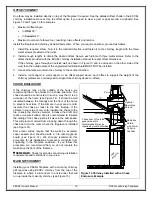
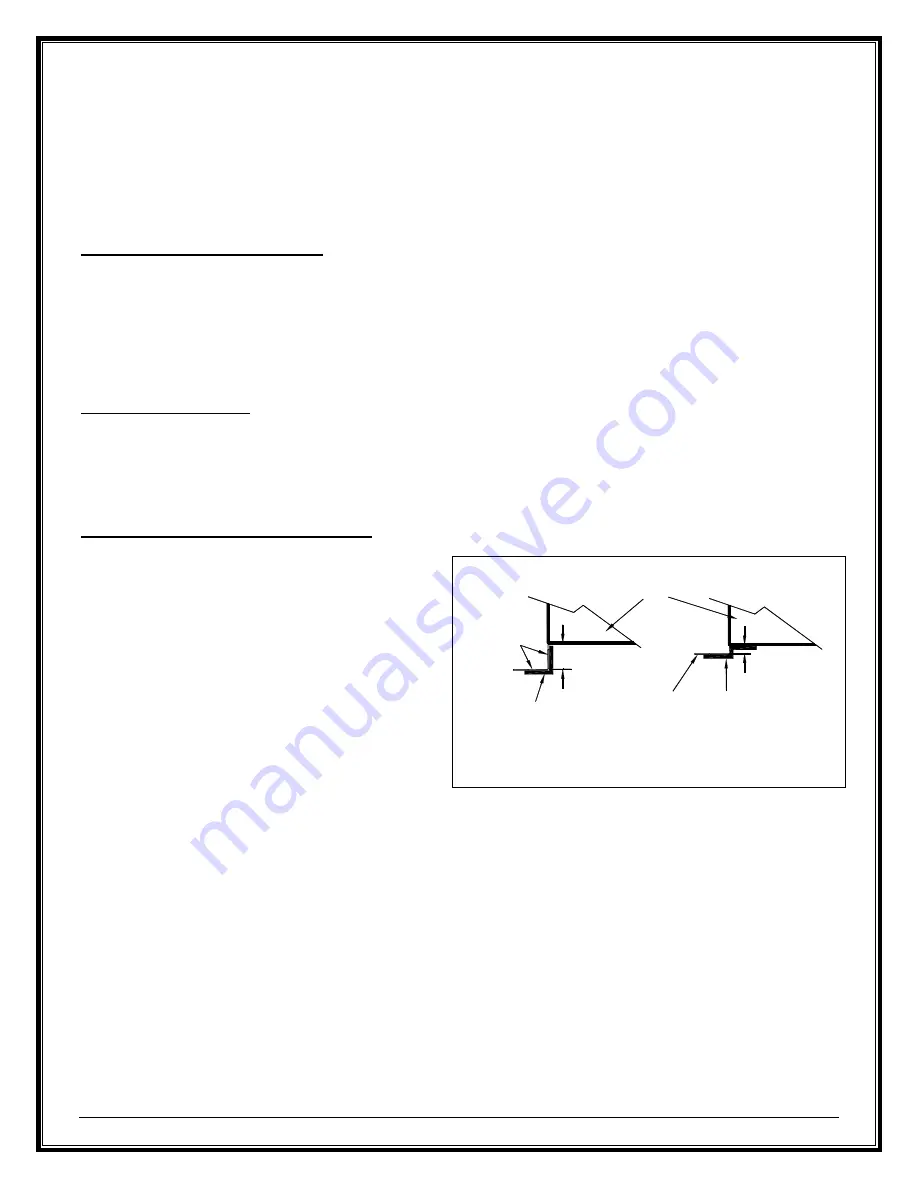
If you are preparing a raised installation, you will need 
a custom made spark guard, either a "Z" shaped 
spark guard or a right angle spark guard (see Figure 16). The Z-shaped spark guard must be used if the height 
between the bottom of the fireplace and the top of the non-combustible flooring of the hearth extension is less 
than or equal to 2 ½". The height of the Z-shaped spark guard must equal the distance between the floor and the 
base of the unit and go under the hearth extension and the fireplace by at least 2½". If the unit is installed higher 
than 2 ½" from the top of the flooring, a right angle spark guard is necessary. The sides of the right angle spark 
guard should be at least 2½" x 2½" and must be covered with non-combustible material. Any custom made spark 
guard must have the minimum width specified in Table 1(I), and be installed centered on the door opening. 

 NOTE

: Custom-made spark guards are site built.  

In the USA only: 

A ½" cement board, such as Durock®, HardieBacker ® or equivalent, MUST be installed beneath the hearth 
extension. The cement board must have the same minimum dimensions as the hearth extension (see Table 1 
(G-H)). If the fireplace is raised by at least 4", the cement board is NOT required. 

The spark guard must be installed under any of the layers of the hearth extension. 

Figure 16  Special Custom-made Spark Guard 

Non-
Combustible
Flooring

Right Angle

Spark Guard
(not provided)

More than 2 1/2"

Non-
Combustible
Flooring

Z-Shaped Spark
Guard (not

provided)

2 1/2" or less

RSF

Fireplace

Summary of Contents for PEARL

Page 1: ...al Residential Factory Built Fireplace Operation Maintenance Installation PEARL Keep these instructions for future use Industrial Chimney Company Inc 400 J F Kennedy St Jerome QC Canada J7Y 4B7 Telephone 450 565 6336 www icc rsf com ...

Page 2: ... 2014 TABLE OF CONTENT SAFETY FIRST 3 DO S AND DONT S 3 CREOSOTE FORMATION AND REMOVAL 3 GENERAL SPECIFICATIONS 4 THE COMBUSTION CONTROL SYSTEM 4 OPTIONS 4 UNIT DIMENSIONS AND CLEARANCES 5 OPERATION 7 AIR CONTROLS 7 BURN TIME VS HEAT OUTPUT 7 FUEL 7 FIRST FIRES 8 LIGHTING 8 REFUELING 8 TROUBLESHOOTING PROBLEMS 8 MAINTENANCE 9 GENERAL CLEANING 9 PAINT 9 GLASS CLEANING 9 CHIMNEY CLEANING 9 DISPOSAL ...

Page 3: ...st 4 away from the front of the fireplace 8 DO NOT use a fireplace grate or other products not specified for use with this fireplace NOTE We strongly recommend that our products be installed and serviced by professionals who are certified by the National Fireplace Institute in the U S or by Wood Energy Technology Transfer Inc in Canada CREOSOTE FORMATION AND REMOVAL When wood is burned slowly it p...

Page 4: ...ount of warm air from the fireplace to another room we offer the Heat Dump Kit FO HD It includes a 180 cfm blower and is most often used to provide supplemental heating to a basement room when the fireplace is on the main floor but it can also be used to send the warm air to an adjacent room or upstairs Decorative andirons FO A are also an optional feature The decorative andirons are made of cast ...

Page 5: ... AND CLEARANCES For the side wall clearance Distance from the fireplace side standoff to the side of the firebox opening 81 8 For the mantel shelf clearance Distance from the fireplace base to the top of the firebox opening 22 Figure 1 Unit Dimensions and Clearances ...

Page 6: ... for other mantel sizes 12 305 mm K Minimum height of a combustible mantel shelf above the top of the firebox opening to the bottom of the combustible mantel refer to the Installation Mantel section for particulars See Table 2 Table 2 Various Mantel Shelf Depths and Corresponding Installation Heights Maximum Mantel Shelf Depth Minimum Installation Height 0 to 4 17 12 28 No combustible mantel shelf...

Page 7: ...more hot air flow up the chimney which means you are sacrificing efficiency Fast burning fires lots of air go through much more wood than slow burning fires To get the most out of your PEARL fireplace adjust the combustion air control lever at the appropriate time If the fire seems to be burning too quickly turn the air down If the fire is smoldering and there are no visible flames turn the air up...

Page 8: ...several pieces as it rises and has air gaps to flow through Continue to leave the door slightly open until the cordwood is lit Close the door completely when the fire is established if the fire goes out you ve shut the door too early To get maximum efficiency out of your fireplace you will want to adjust the amount of air entering the firebox at the appropriate times Gauge how much to close the co...

Page 9: ...rfectly clean A good hot fire once a day usually cleans off most of the deposits that have accumulated Remember the drier the wood and the hotter the fire the cleaner the glass A word of caution although heat will not break the glass impact can Be careful not to hit the glass WARNING NEVER CLEAN THE GLASS WITH AN ABRASIVE CLEANER UNLESS SPECIFIED FOR THAT PARTICULAR USE USE ONLY A CLEANER RECOMMEN...

Page 10: ...cy over firing excessive wood consumption and premature fireplace failure INSTALLATION Check with your local authority having jurisdiction such as municipal building department fire department fire prevention bureau etc regarding restrictions and installation requirements and the need to obtain a permit NOTE We recommend that you remove the door until after all finishing work is completed around t...

Page 11: ...hin Facing 24 61 86 Thick Facing 23 60 85 The framing dimensions are larger than required for ease of installation The Heat Dump Option will require an extra 12 on the selected side Figure 4 PEARL Framing Examples FRAMING The enclosure walls can be framed with any suitable materials 2x4 or 2x6 studs plywood gypsum board etc Because of the high heat output potential of the PEARL combustible materia...

Page 12: ...he Attic Ceiling Radiation Shield Hearth Extension and Beneath Hearth Extension refer to text for particulars Outside Air Inlet refer to text for particulars Connects to the left side of the fireplace No combustible material over the fireplace facing top stand off and in front of the top casing grayed area refer to text for particulars Cold air trap optional ...

Page 13: ...sing of the fireplace to the floor If possible try to have at least one if not two of the brackets screwed into the floor joists with 2 wood screws OUTSIDE AIR DUCT After the fireplace is correctly positioned connect the outside air inlet to the fireplace Use an insulated aluminium flexible duct rated at over 200 F The duct should not exceed 12 vertical rise above the base of the unit We suggest u...

Page 14: ... base of the fireplace Do not lose the hardware that secures the faceplate to the fireplace To remove the bottom louver simply open the door grab the top of the louver close to each extremity and pull forward There are two high temperature magnets one on each side close to the top of the louver keeping it in place along with two supports close to the bottom of the louver to support the weight of t...

Page 15: ...le material such as a cement board Use the template provided in the cardboard packaging of the fireplace to cut the cement board to the appropriate shape The decorative faceplate will cover the edge of the cement board against the fireplace casing Remember ONLY NON COMBUSTIBLE MATERIAL SUCH AS CEMENT BOARD CAN TOUCH THE FIREPLACE CASING The rest of the wall beyond the standoffs can be covered with...

Page 16: ...s that will result in a combined thickness greater than 1 e g brick stone etc These materials will not fit behind the decorative faceplate and will protrude past the faceplate once installed If you are using thick finishing materials then the decorative faceplate of the Pearl can be used as a template Flat Facing requires cement board due to the direct contact to the fireplace casing Thin Facing 1...

Page 17: ... 20 24 21 26 6 9000 10000 16 6 17 6 19 20 6 24 6 22 27 CHIMNEY INSTALLATION Make sure to read the EXCEL Chimney installation manual concerning requirements for supports bracing anchors etc Refer to Table 1 F for the maximum chimney height that can be supported by the top of the fireplace WARNING THE CLEARANCE BETWEEN THE CHIMNEY AND COMBUSTIBLE MATERIAL MUST BE 2 OR MORE DO NOT FILL THIS AREA WITH...

Page 18: ...tightly in place Figure 12 Offset Chimney Installation Example Figure 13 Offset Chimney Through a Wall Example Radiation Shield Use Offset Support or Roof Support R SF Fireplace Radiation Shield 3 Metal Screws in Each Joint Rise Offset 10 2 min Flashing with Storm Collar 1 min Radiation Shield and Offset Roof or Wall Support Insulated Wall Radiation Shield 30 or 45 In USA use a vented flashing In ...

Page 19: ...d in a chase structure The chase should be constructed in such a way that it is an extension of the home see Figure 14 It should be well insulated between the footings and the floor of the home to prevent heat loss If the climate in your area is mild insulate the chase at least to the first firestop If the climate in your area is very cold insulate the chase to the top to keep the chimney warmer i...

Page 20: ...l constructed and fully lined in accordance with Local Building Codes and the National Building Code of Canada NBC or National Fire Protection Association chimney standard NFPA 211 2 It has been thoroughly cleaned of any soot or creosote residue and inspected to determine that it is in good working condition 3 There is no insulation of any type in contact with the masonry chimney and there is no i...

Page 21: ...ed on a non combustible floor NONE of the cement board and the spark guard specified below is not required Install the spark guard provided 5 x 36 piece of sheet metal halfway under the fireplace and halfway under the hearth extension and centered on the door opening The spark guard will extend 2 beneath the fireplace This will make certain that sparks cannot lodge in this area and start a fire If...

Page 22: ... top front of the firebox To do so unscrew the bracket located on the left side of the tube 2 Place the baffle 1 above the other two tubes and ensure its proper orientation narrow part towards the rear and grooves towards the bottom 3 Reinstall the first tube and screw it in place 4 Continue by inserting the rear refractory brick in the firebox 2 then the left side refractory brick 3 5 Then insert...

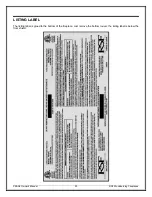
Page 23: ...PEARL Owner s Manual 23 RSF Woodburning Fireplaces LISTING LABEL The listing label is glued to the bottom of the fireplace Just remove the bottom louver the listing label is below the floor shield ...

Page 24: ... OPTIONS LIST Electricity Required FO A Decorative Andirons FO DUCT5 Insulated Duct 5 feet FO GRK9 Gasket Replacement Kit FO FDHB8 Internal Blower Kit FO FDM7 Masonry Chimney Adapter 7 FO HD Heat Dump Kit FO INT Outside Air Kit 4 Diameter FO V2 Gravity Vent Kit ...

Page 25: ...PEARL Owner s Manual 25 RSF Woodburning Fireplaces REPLACEMENT PARTS Use only genuine RSF parts The use of any substitutes will void the warranty and may put your safety at risk AVAILABLE SOON ...

Page 26: ...s eroded or cracked refractory components Repairs or replacements necessitated by vandalism neglect abuse over firing improper fuel or fuel loads or failure to adequately service the unit as stated in the owner s manual Repairs or replacements particularly charges for travel and labor not authorized by RSF Woodburning Fireplaces in advance LIMITATIONS All items found to be defective will be replac...

Reviews: