background image

ORACLE

page 16

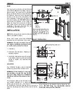
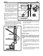
2. The grill adaptor is designed to be installed underneath

the gypsum board in the wall. In the desired location,
frame a 13" x 13" hole to accept the gravity vent grille
adaptor. Fit the gravity vent grille adaptor into the framed
hole and fasten it into place with nails or screws.

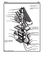
3. Remove the outer cover to the left, right, or both sides

of the flue outlet, on the ORACLE.

4. Cut the insulation to the size of the opening and remove

the cover plate underneath (it is taped in place).

5. Install the B-vent starter section. The slot in the B-vent

starter section should be facing the front and the hole
should be facing the back. Bend up the four tabs at the
base of the starter section to hold it in place.

6. Install the "shut off" damper at the base of the starter

section. The shut off damper enables the manual con-
trol of hot air flowing through the gravity vent pipe. With
the top louvers removed and the angular portion of the
rod in hand, insert the damper rod into the hole in the
starter section. Next, make sure that the washer and
spring on the control arm are both on the outside of the
starter section and that the rod has fit snugly into the
slot. A definite tension should exist between the shut off
damper rod and the starter section. Replace the lou-
vers. The damper rod should protrude above the top of
the louvers.

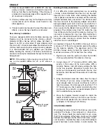
7. Install the B-vent pipe, between B-vent starter and the

grille adaptor. Fasten each joint with 3 screws. Insert the
B-vent pipe into the grille adaptor and fasten it with three
screws. The B-vent pipe needs only be inserted far
enough to be able to screw it into place. This allows you
about 3 ½" of adjustment.

8. Once the wall facing around the gravity vent grille adap-

tor has been completed, install the grille with the sup-
plied screws. The gravity vent is now ready for opera-
tion.

GAS LOG OPTION

The Oracle now features a gas conversion option. You can
use your choice of gas log sets with this conversion. The
installation of the gas should only be done by qualified per-
sonnel. To convert the Oracle for use with the gas log
option:

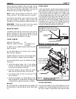
1. You will notice a 1 ¼" diameter knockout on both sides

of the Oracle, about 9" up from the bottom of the fire-
place (see Figure 4). The gas line will be installed
through one of these knockouts.  Choose the side that
is best for your installation.

2. Remove the firebrick from the base of the firebox. You

will notice two sheet metal pieces underneath the fire-
brick. Remove these also. Keep the firebrick and sheet

metal, as they will be needed to operate the Oracle, if
you would like to burn wood again.

3. Underneath the firebrick and sheet metal, there are four

1" diameter holes in the center of the bottom, to bring air
to the gas log set. These holes must not be blocked.  

4. There are two 1 ¼" diameter holes closer to the sides of

the bottom of the firebox. If you are installing a gas
valve, install it over one of these larger holes, to allow
the airflow to cool the gas valve.

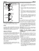
5. When you remove the firebrick you will notice a notch in

the bottom of the side refractories. The gas line will
come through one of these notches (see Figure 19).

6. Follow the instructions supplied with your gas log set

concerning the installation of gas lines, shut-off valves,
etc. If you have the sand pan type of gas log set that
covers the air holes, place some of the firebrick, or
some other suitable non-combustible material around
the edges of the sand pan to raise the gas log set above
the air holes.

Maximum gas input: 40 000 BTU

There are no minimum clearances to the sides or top of the
firebox. However, any clearances stated by the gas log set
manufacturer must be maintained.

You may install the gas valve inside the firebox if the gas log
set manufacturer allows this in its instructions, and the
required clearances are met.

gas knockout

13 1/4”

gas log set of
your choice

Figure 19: Gas log option

4”

Summary of Contents for The oracle

Page 1: ...RSF IIR_03 06 Keep these instructions for future use THE ORACLE Owner s Manual Residential Factory Built Fireplace Operation Maintenance Installation ...

Page 2: ...ing 15 The Gravity Vent System 16 Gas Log Option REPLACEMENT PARTS 17 Fireplace 18 Assemblies LABEL 19 WARRANTY 20 ORACLE page 2 Dear Customer The ORACLE fireplace incorporates technology with elegance to give you a beautiful view of the fire without compromising on heating efficiency or environmental quality We have designed your new ORACLE to be easy to install operate and maintain It is in your...

Page 3: ...s occurred If a significant layer of creosote has accu mulated or more it should be removed to reduce the risk of chimney fire WARNING Burn dry wood only DO NOT Burn driftwood coal garbage plastic treated wood Do not use construction scraps e g 2x4 or plywood scraps as your only supply of fuel as this may overheat and seriously damage the fireplace Use no more than 3 densified fuel logs e g Presto...

Page 4: ...place are placed in the fireplace at the factory If for any reason they should need to be replaced the following order should be observed The baffle R4301 should be passed into the firebox with the holes towards the floor of the box Supporting the baffle from the bottom and holding it as high as it will go while the side refractories R4303 and R4302 are put into position to hold the baf fle into p...

Page 5: ...amic glass a good blow can NEVER clean this glass with an abrasive cleaner Use only a cleaner recommended by your dealer Never clean the glass while it is hot Do not operate the fire place with the glass broken or removed If your glass breaks See your dealer for the exact replacement glass If the gasket is damaged it must be replaced with the identi cal kind R7000 Place the gasket around the top a...

Page 6: ...ge because of muriatic acid plaster cement paint and harmful sprays or liquids and sub trade tool abrasion LOCATION Your ORACLE fireplace may be installed without any special floor reinforcement WARNING If this fireplace is not prop erly installed a house fire may result For your safety follow the installation directions and heed the minimum clear ances The enclosure walls can be framed using any ...

Page 7: ...d enclosure fresh air hood 23 minimum depth of opening less the sheeting on both sides electrical knockouts 5 wide sheet metal spark guard storm collar roof flashing radiation shield and storm collar ceiling radiation shield header ORACLE see the manual for flue height requirements gravity vents may be installed on the left right or both sides hearth extention The hearth can be made of any permane...

Page 8: ...he top of the unit to be less than 32 inches See Figure 2 OUTSIDE AIR DUCT After the fireplace is correctly positioned connect the combustion air inlet to the outside see Figure 5 A 4 inch diameter duct can be used if the total run of the pipe is less than 25 feet If the total run is longer than 25 feet a 5 inch diameter pipe must be use 1 Find a convenient location for the combustion air duct and...

Page 9: ...ial must not be less than 2 DO NOT fill this area with insulation 1 Cut and frame the required holes in the floor ceiling and roof where the chimney will pass through Use a plumb bob The framing size is 14 square page 9 TABLE 1 MINIMUM RECOMMENDED FLUE HEIGHTS IN FEET FROM THE TOP OF THE FIREPLACE NUMBER OF ELBOWS Elevation ft 0 2 x 15 4 x 15 2 x 30 4 x 30 2 x 45 4 x 45 0 1000 12 13 14 15 18 16 20...

Page 10: ...in place 7 Wash the roof flashing with solvent or vinegar if the flashing is galvanised then paint it with exterior paint 8 Read and follow the Excel chimney installation man ual concerning requirements for supports bracing s anchors etc MASONRY CHIMNEY WARNING When contemplating using an existing chimney it must first be thoroughly inspected by an authority having jurisdiction to determine the fo...

Page 11: ... replace the clay liner After mortaring in place the connection should not be visible Care must be taken when cleaning to ensure that the stainless steel flex liner is not dislodged As depicted in Figure 8 the EXCEL chimney is to be a minimum of 18 from the connection point at the elbow to the masonry adaptor The uppermost part of the EXCEL chimney where it enters the masonry chimney must be a min...

Page 12: ...cure each joint with 3 metal screws 3 Use another elbow to return the chimney to the vertical direction 4 Install a roof support or an offset support at each offset to support the weight of the flue elbows are not designed to support a flue above an offset SEALING Be sure to seal the space between the fireplace and the standoffs with a bead of silicone sealer See Figure 13 SPARK GUARD Install a 5 ...

Page 13: ...me size Wipe off all fingerprints etc with a soft cloth and mild soap and water FACING Facing materials may only be non combustible such as metal brick rock concrete board or ceramic tile Gypsum board is NOT an acceptable facing material If you desire to fully face the fireplace with thin mason ry it is recommended that you purchase the rock retain er kit part FDKO This kit is NOT recommended for ...

Page 14: ...metall FDKO 9 10 metal screws framing finishing trim stabilizing bracket metal edging Figure 15 Installation of rock retainer FDKO Warning allow room for the handle and opening the door wide when placing rock facing finishing trim stabilizing bracket plywood hearth stone tile or brick mortar heavy expanded metal part FDKO wire mesh ...

Page 15: ...m incorporates standard 8 B vent components for installation Single wall pipe is not allowed due to the high temperature of the air in a grav ity vent system Any listed brand of 8 B vent pipe may be used and is not a part of the FDVO The maximum pipe length is 15 ft from the top of the fireplace to the outlet Remember double wall black pipe from ICC can be used instead of B vent pipe NOTE If two g...

Page 16: ...LOG OPTION The Oracle now features a gas conversion option You can use your choice of gas log sets with this conversion The installation of the gas should only be done by qualified per sonnel To convert the Oracle for use with the gas log option 1 You will notice a 1 diameter knockout on both sides of the Oracle about 9 up from the bottom of the fire place see Figure 4 The gas line will be install...

Page 17: ...AA1212W AA1211 AA1242W R7005 R7000 A1214 3 A1210 R6012 R1850 A1214 1 R6410 AA1430W R7008 R4301 R4302 R4303 R4304 R4305 R4306 AA1088W AA1089 A1433 A1448W A1412 Louver fin black Louver fin gold Louver fin pewter Louver hardware assembly Nut 1 4 20 Hex Louver rod Spacer 1 4 X 1 3 8 Retention spring for louvers Door glass Door frame Door hinge assembly Door channel bottom black Door channel top black ...

Page 18: ...AA1212W AA1211 AA1242W R7005 R7000 A1214 3 A1210 R6012 R1850 A1214 1 R6410 AA1430W R7008 R4301 R4302 R4303 R4304 R4305 R4306 AA1088W AA1089 A1433 A1448W A1412 Louver fin black Louver fin gold Louver fin pewter Louver hardware assembly Nut 1 4 20 Hex Louver rod Spacer 1 4 X 1 3 8 Retention spring for louvers Door glass Door frame Door hinge assembly Door channel bottom black Door channel top black ...

Page 19: ...ACLE page 19 We recommend that our products be installed and serviced by professionals who are certified in the U S by NFI National Fireplace Institute or in Canada by WETT Wood Energy Technical Training ...

Page 20: ...Repairs or replacements necessitated by vandalism neglect abuse over firing improper fuel or fuel loads or failure to ade quately service the unit as stated in the owner s manual Repairs or replacements particularly charges for travel and labor not authorized by RSF Woodburning Fireplaces in advance LIMITATIONS All items found to be defective will be replaced or repaired upon return of the defecti...

Reviews: