DT2306 Potentiometer Data Logger Manual
ELM0075B
Page 12
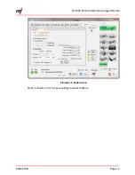
F
IGURE
4-4
T
HE MONITOR TAB
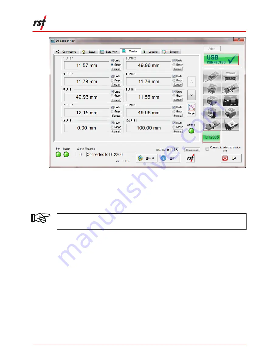
Opening the monitor tab sets the data logger into monitor mode. The screen reports
in % of the detected potentiometer ratio by default.
Click the check boxes to change the display to Engineering Units.
NOTE:
E
NGINEERING
U
NITS ARE ONLY AVAILABLE WHEN SENSOR CALIBRATION DATA
AND CONVERSION METHOD IS SET IN THE
S
ENSORS
T
AB
.
The sensor reading will update approximately every two seconds when successfully
connected to the data logger. A green indicator will flash each time a sensor data is
updated.
The program will display "----" in each Sensor Reading field until communication is
established with the data logger.
The program will display "RANGE_ERR" when the Sensor Reading is outside of
valid range.
4.4.1
Graphical Monitor
Click the 'Graph' button to invoke the data logger graphical monitor. The graphical
monitor displays the recently monitor readings in a Sensor Reading vs. Time graph.
The graphical monitor will update approximately every two seconds when
successfully connected.


