RSTAR Affinity
Data Logger
Installation Guide
PSM0003A
RST Instruments Ltd.
Page 5
IIM
Type
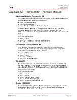
Terminal Pin
1
Terminal Pin
2
Terminal Pin
3
Terminal Pin
4
Terminal Pin
5
VW*/TH* Shield
VW 1
VW 1
Thermistor 1
Thermistor 1
VW/TH
Shield
VW 1
VW 1
VW 2
VW 2
VW/TH
Shield
Thermistor 1
Thermistor 1
Thermistor 2
Thermistor 2
TH/TH
Shield
Thermistor 1
Thermistor 1
Thermistor 2
Thermistor 2
RS-485
Shield
Ground
+12V Output
RS-485 - B
RS-485 - A
4-20mA
+12 Output 1
Shunt 1
+12V Output 2 Shunt 2
Table 1: IIM Pin Assignment
*VW stands for vibrating wire
**TH stands for thermistor
2.4
C
ONNECTIVITY
The data logger comes with options for different instrument interfaces. The
connectors on the enclosure include up to five port cable glands and/or Quick
Connect cables for sensors and instruments, and a LoRaWAN external antenna.
2.4.1
Quick Connect
The Quick Connect option on the data logger is IP67-rated and can be used in
harsh environments. It simplifies field installation and is ideal where sensors are
frequently replaced. The connectors are installed by RST for specific
instruments. There are no modifications required for the Quick Connect option.
2.4.2
LoRaWAN External Antenna
The data logger can use either a factory installed LoRaWAN antenna (mounted
inside the enclosure) or an optional external antenna (using the data logger’s
type-N connector). Refer to the data logger’s configuration identification label
(discussed in section 3.2.1) to see if your data logger comes with a built-in
antenna.
The LoRaWAN network operates in three radio frequency bands. If you are using
an optional external LoRaWAN antenna, refer to Table 2 for the recommended
antennas to match the different bands.
Band
Antenna Recommendation
Gain
Dimensions
900-928 MHz Taoglas Blade 868/ 915Mhz Omnidirectional
1 dBi
228 x 23 mm
863-870 MHz Taoglas Blade 868/ 915Mhz Omnidirectional
1 dBi
228 x 23 mm
433 MHz
Taoglas OMB.433.B06F21
6dBi
1473 mm
(max) x
24mm
Table 2: Recommended LoRaWAN Antenna


