background image


Real Time Automation, Inc. 

42 

1-800-249-1612 


Appendix C: Create User Defined Tag in RSLogix 5000 

1)


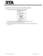
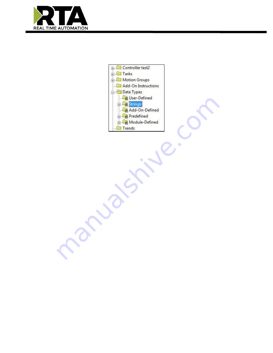
Within RSLogix 5000, click on 

Data Types

 and select 

Strings

.  


2)


Right click on String and select 

New String Type

. Give the new data type a name.  

3)


Select the max number of characters to be transferred.  

4)


When creating the tag name in the PLC, select the name of the new user defined data type you 
just created. 

Summary of Contents for 490NBX-NNA1

Page 1: ...Real Time Automation Inc 1 1 800 249 1612 490NBX NNA1 ASCII to PLC Gateway Product User Guide Revision 8 02 Platform NNA1 ...

Page 2: ...sion or limitation of incidental or consequential damages therefore the limitations set forth in this agreement may not apply to you No patent liability is assumed by Real Time Automation with respect to use of information circuits equipment or software described in this manual Government End Users If this software is acquired by or on behalf of a unit or agency of the United States Government thi...

Page 3: ...Client Device is Connecting to the Gateway Acting as a Server 16 Setting up ASCII to PLC Communication 17 Define PLC Tag File 17 Define ASCII Message Termination 18 Message Queue 19 Data Conversion 19 Setting up PLC to ASCII Communication 20 Define PLC Tag File 20 Add Delimiters to ASCII Message 21 Data Conversion 21 Diagnostics and Troubleshooting 22 PLC Status 22 Diagnostics and Troubleshooting ...

Page 4: ... Save and Replace Configuration using SD Card 35 Data Transfer To From SD Card 35 Using IP Setup with SD Card 35 Appendix A Error Definitions 36 Appendix B I O Messaging Configuration Rev 7 03 or Later 40 Input Output Assembly Byte Breakdown 40 Input Output Assembly Handshaking Breakdown 41 ASCII to PLC 41 PLC to ASCII 41 Input Output Assembly Diagnostics Breakdown 41 Appendix C Create User Define...

Page 5: ...exLogix MicroLogix PLC5E SLC or other legacy PLC featuring a NetENI module Tools and documents available online http www rtaautomation com product 490 nbx support If at any time you need further assistance do not hesitate to call Real Time Automation support Support Hours are Monday Friday 8am 5pm CST Toll free 800 249 1612 Email support rtaautomation com ...

Page 6: ...Real Time Automation Inc 6 1 800 249 1612 Hardware Powering the Gateway An 8 24 VDC power source to the gateway Red Wire Black Wire a The unit draws 175mA 12V ...

Page 7: ... under the DIN Rail 3 While pressing the 490NBX against the rail press up to engage the spring loaded lower clip and rotate the unit parallel to the DIN Rail 4 Release upward pressure Removing Follow these steps to remove your interface converter 1 Press up on the unit to engage the spring loaded lower clip 2 Swing top of the unit away from the DIN rail Spring Loaded Lower Clip DIN Rail ...

Page 8: ... also on the network Refer to the Accessing_Browser_Configuration doc on the cd to setup DHCP on your PC Run the IPSetup exe program from the CD ROM Find unit under Select a Unit a To change the IP Address to match that of your PC if DHCP has failed enter the desired static IP settings on the left hand side and click Set i You will know DHCP has failed if the gateway s IP address is AutoIP at 169 ...

Page 9: ... Default Gateway 2 The gateway must be on the same Network Subnet as the PC whether its setup for DHCP Static Once you have both devices on the same network you should be able to ping the gateway using a MS DOS Command Prompt The Screenshot above shows a gateway that is currently set to a static IP Address of 192 168 0 100 If you are able to successfully ping your gateway open a browser and try to...

Page 10: ...l the gateway is restarted When all desired changes have been made press the Reboot button The webpage will redirect to our rebooting page shown below The reboot can take up to 20 seconds You will know the save was successful if the red box is no longer present o If the IP address has not been modified the gateway will automatically redirect to the main page o If the IP address was modified a mess...

Page 11: ...reen box below You can easily navigate between pages Main Configuration Diagnostics and Other pages using the buttons on the left hand side Device Status orange box below This quickly shows the high level status of any ASCII Ports that are enabled in the Serial Configuration The values on this page mimic the same values that are displayed on the Diagnostics Page ...

Page 12: ...tton which is located next to Device Configuration 2 This allows you to edit the Device Description IP Settings IP Address Subnet Default Gateway and Ethernet Link settings 3 To save all values click the Save Parameters button NOTE Once Save Parameters is pressed new IP Settings take effect immediately ...

Page 13: ...he PLC a If using I O Scanner this is the IP Address of the PLC i If the IP Address is 0 0 0 0 the gateway will accept messages from any device 4 Controller Slot Enter the slot that the Controller is located in a If you are using an Integrated Ethernet Card enter slot 0 b For Logix processors this is NOT the slot of the Ethernet Adapter 5 Communication Mode Select whether to use unconnected or con...

Page 14: ...d generate the most traffic c In applications with a heavy network it is recommended that you increase this delay to limit network traffic 7 Heartbeat Tag File This Tag or File will act as an incremental counter for messages passed though the gateway a For RSLogix5000 Family This should be an INT Data Type Tag b For RSLogix500 Family This should be an N Register c This can be used to monitor if th...

Page 15: ...ress Enter the IP address of the Server that the gateway will open a TCP IP Connection to The combination of IP Address and TCP Port must match the device exactly in order for the gateway to open a connection 4 TCP Port Enter the TCP Port Number that the Server is communicating on The combination of IP Address and TCP Port must match the device exactly in order for the gateway to open a connection...

Page 16: ...y IP Address to make the Connection The combination of the IP Address and TCP IP Port must match the device exactly in order for the device to open a connection to the gateway 3 TCP Port Enter the TCP IP Port Number on which the Client is communicating The combination of the IP Address and TCP IP Port must match the device exactly in order for the device to open a connection to the gateway 4 Inact...

Page 17: ... PLC Type configured is I O Scanner then this field is not used 2 Enter the Tag File name you want the gateway to move the ASCII message to a The Tag File must be defined in the PLC and must match exactly b Most of the time the Tag Name is defined within the Controller Scope of the PLC for Read Write Access i To configure our gateway for a Program Scope Tag see Appendix D for instructions c If PLC...

Page 18: ...data type is STRING 1 82 characters INT 1 200 characters SINT Not Used b Timer Use this option if your device sends data of varying lengths and does not have end delimiters This is the amount of time we will wait after the last character of a message before considering the message complete c Delimiters i Start Select how many Start Delimiters to look for in the ASCII message Use this feature if th...

Page 19: ...one of the following ways a Discard New Data Gateway will discard any new messages b Overwrite Oldest Data Gateway will overwrite oldest message with new data Data Conversion 1 NULL Character Handling Select how the gateway will handle the NULL Character a None Default Does no additional conversion on the data before sending it to the PLC b Remove NULL Removes all NULL characters from the ASCII Me...

Page 20: ... Access i To configure our gateway for a Program Scope Tag see Appendix D for instructions c If PLC Type configured is I O Scanner then this field is not used 3 Character Count Enter the maximum number of characters that the gateway can send to the ASCII device a If using an INT Data Type this is also the dimension size 2 1 of the Tag File b If using a SINT Data Type this is also the dimension siz...

Page 21: ... End Use this feature to add a common end delimiter s to messages being sent to the ASCII device i The value of this first dropdown will either gray out or allow a delimiter to be selected from the next dropdown ii Use this feature only if your ASCII device requires such delimiters iii All ASCII messages will receive the end delimiters selected Data Conversion 1 Data Conversion a None Default Does...

Page 22: ...s See section Diagnostics Main Page for further explanations Connection Attempts This value increments every time the 490NBX loses connection to the PLC and attempts to reconnect Write Heartbeat to PLC OK Number of successful write messages to heartbeat Tag File Name Error Number of failed write messages to heartbeat Tag File Name Last Error Specific error information pertaining to the last failed...

Page 23: ...set to zero indicating the last message has been processed When using String Data Type the LEN needs to be set to 0 When using INT Data Type the 1st array index 0 needs to be set to 0 When using SINT Data Type the 1st and 2nd array index 0 1 needs to be set to 0 Current message being processed chars This buffer shows the real time data that the ASCII device is sending out to the 490NBX gateway All...

Page 24: ...uffer being full Read Handshake Message from PLC OK Increments when the length field is non zero in the PLC Error Increments when there is an error with the Tag File in the PLC Last Error This will report the most recent error Note Errors that show up here are reported from either the 490NBX or the PLC For detailed errors and explanations please see Appendix A Write ASCII Message to PLC OK Increme...

Page 25: ... will process it and then set to 0 indicating another message can be sent When using String Data Type length is set using the LEN field When using INT Data Type the length is the 1st array index 0 When using SINT Data Type the length is the 1st and 2nd array index 0 1 Send Test Message to ASCII Use this field to bypass the PLC and send a test message out to the ASCII device from the gateway All de...

Page 26: ...rrors that show up here are reported from either the 490NBX or the PLC For detailed errors and explanations please see Appendix A Write Handshake Message to PLC OK Increments with every successful message sent from PLC to the ASCII device Error Increments when there is an error with the Tag File Name in the PLC Last Error This will report the most recent error found Note Errors that show up here a...

Page 27: ...id and are communicating with the gateway within the Inactivity Timeout configured Blink Red 1 Data Timeout No data within Inactivity Timeout 2 Queue is full and gateway is discarding messages Solid Red 1 No TCP Devices configured enabled 2 No ASCII Devices configured enabled Off Ethernet cable is unplugged LED 2 Allen Bradley PLC Blink Green No messages sent or received Solid Green Connection to ...

Page 28: ...ess Controller Slot and Communication Mode to ensure information entered is correct Normally Connection Attempts will also increment with this PLC Status 4 I O Adapter Displays when PLC Type is selected to I O Scanner ASCII Status This shows the overall status of the ASCII devices Possible values are 1 No Serial Port Configured Displays when no ports are configured on the Serial Configuration page...

Page 29: ...h the TCP IP device 3 ASCII to PLC Status and PLC to ASCII Status columns The two right columns break down the communication on that specific port by direction Possible statuses are Disabled Indicates that the direction on that port is not enabled Tag File Not Yet Defined Indicates that the port and direction are enabled but the tag file name is blank o Only when PLC Type is not I O Adapter A deci...

Page 30: ...to save as Any type will suffice 3 This will save all of the configuration except for the Gateway s IP Network Settings since this must be unique 4 Save this file to the PC Import Configuration 1 Click Choose File and search for the configuration to load to the 490NBX 2 Click Load Configuration If successful you will be redirected to the main page and be forced to reboot the gateway a If the load ...

Page 31: ...agnostic purposes Configure security settings Upgrade the firmware right from the webpage Various options to reset the gateway Revision Listing Displays the full catalog number of the gateway Have this number ready when contacting a RTA Technical Support Specialist Diagnostics Logging Most users will not need to do anything with this feature If there are problems with the gateway a RTA Technical S...

Page 32: ...information in case username password is forgotten 6 Click the Save Parameters button to save Security Log In 1 Username Name of the user to login 2 Password Password of the user to login 3 Log In If login is successful the user will be redirected to the Main Page 4 Display Hint Displays the hint specified for the user if one was set up 5 Reset Password This is used to reset security settings Conf...

Page 33: ...d and will automatically reboot the gateway after 30 seconds and redirect the webpage to the Main Page when finished Reset Gateway There are 3 options to reset the 490NBX Restart the Gateway Saves the current settings of the gateway and performs a software reboot Reset to Last Powerup Brings the device back to its last power up settings Reset to Shipped Defaults Brings the device back to its origi...

Page 34: ...ard slot there is a small pinhole Using a small paperclip press the button through this pinhole and hold the button for at least 5 seconds 2 After 5 seconds the unit will acknowledge the command and the Comm LED see section Diagnostics and Troubleshooting LEDs will go to Blink Green at 100ms 3 Release the button and the gateway will reset to default DHCP IP settings Refer to the Accessing_Browser_...

Page 35: ...rd contains a configuration that differs in any way from the configuration already in the gateway the configuration from the SD card will be applied NOTE When data is being written from the SD Card to the gateway it will take up to 30 seconds for the data transfer to be completed During this time the gateway cannot be accessed via the webpage Using IP Setup with SD Card When an SD Card is present ...

Page 36: ...tained in the processing node Path processing shall stop when a path destination unknown error is encountered 0x06 Partial transfer Only part of the expected data was transferred 0x07 Connection Lost The messaging connection was lost 0x08 Incorrect Controller Slot The requested service was not implemented or was not defined for this object class instance 0x09 Invalid attribute value Invalid attrib...

Page 37: ...ver fragmentation sequence The fragmentation sequence for this service is not currently active for this data 0x18 No stored attribute data The attribute data of this object was not saved prior to the requested service 0x19 Store operation failure The attribute data of this object was not saved due to a failure during the attempt 0x1A Routing failure request packet too large The service request pac...

Page 38: ...ements of this specification and or the requirements defined in an Application Object Specification 0x21 Write once value or medium already written An attempt was made to write to a write once medium that has already been written or to modify a value that cannot be changed once established 0x22 Invalid reply received An invalid reply is received This status code can serve for other causes of inval...

Page 39: ... not able to be set at this time 0x28 Invalid member ID The Member ID specified in the request does not exist in the specified Class Instance Attribute 0x29 Member not settable A request to modify a non modifiable member was received 0x2C Attribute not gettable A request to read a non readable attribute was received ...

Page 40: ... Configuration Assembly Any number unused Configuration Size 0 bytes Input Output Assembly Byte Breakdown Input Assembly ASCII to PLC Port 0 Input Assembly ASCII to PLC Port 1 Bytes 0 1 Output Handshake Bytes 208 209 Output Handshake Bytes 2 3 Input Sequence Number Bytes 210 211 Input Sequence Number Bytes 4 7 Input Length Bytes 212 215 Input Length Bytes 8 207 Input Data 0 200 bytes Bytes 216 415...

Page 41: ...arded based on the discard rules defined by the user The Sequence Number will roll over to 1 after 65535 PLC to ASCII If the Output Sequence Number matches the Output Handshake the PLC can write a new message to the 490NBX The PLC must write the Output Length and Output Data first then increment the Output Sequence Number Once the message is processed by the 490NBX the Output Handshake is echoed w...

Page 42: ...thin RSLogix 5000 click on Data Types and select Strings 2 Right click on String and select New String Type Give the new data type a name 3 Select the max number of characters to be transferred 4 When creating the tag name in the PLC select the name of the new user defined data type you just created ...

Page 43: ... tag name inside of the RTA gateway needs additional syntax for it to successfully communicate EX In the picture below the Controller is set to test2 In the example below the tag AnotherTag is setup in Program Scope named AnotherProgram It is not setup in test2 Controller Scope To access this tag AnotherTag in scope AnotherProgram you need to enter it into the gateway using the following syntax Ta...

Reviews: