R.T.A. s.r.l. – ADW_ME05 – 09/21
16/22
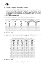
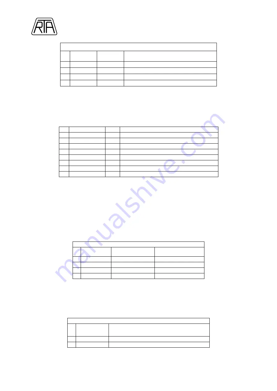
TABLE OF MOTOR LOW SPEED (
DIP 7 and 8 of DP1)
DIP 7
DIP 8
LOW /HIGH SPEED RATIO
►
OFF
OFF
1/9
OFF
ON
1/18
ON
OFF
1/27
ON
ON
1/36*
Table 10
= default factory setting.
(*) Note:
When Analog Input is used and AUTOSTOP is enabled, setting of 1/36 low/high speed ratio is
forbidden.
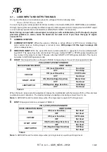
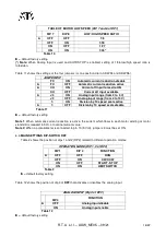
Table 11 shows the settings of the four jumpers (or one position dip in ADW 94 and ADW 96).
JUMPER/DIP
FC
ON
Automatic current reduction disable
►
FC
OFF
Automatic current reduction active
►
CO
ON
Current off input forced to ON
CO
OFF
Current off input available
►
J3
ON
Analog input range (from 0 to 5 V)
J3
OFF
Analog input range (from 0 to 10 V)
f/
ON
Division by 10 speed scale active
►
f/
OFF
Division by 10 speed scale disable
Table 11
= default factory setting.
Note 1
: When automatic current reduction is active, the current which flows in each motor winding at motor
standstill is reduced to 50% of nominal current value.
Note 2
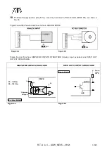
: When a potentiometer is connected to pin 10 (5 Volt), jumper J3 must be set ON.
6.3-
MAIN SETTINGS DIP-SWITCH DP2
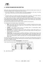
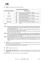
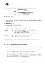
Table 2 shows the position of dips 1 and 2 (DP2) related to different operation modes:
OPERATION MODE (DIP 1, 2 of DP2)
DIP 1
DIP 2
FUNCTION
►
OFF
OFF
RUN
OFF
ON
CW/CCW
ON
OFF
START - STOP
ON
ON
LIMIT SWITCH
Table 2
= default factory setting.
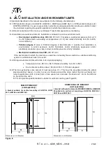
Table 12 shows the position of dip 3 of
DP2
that activates or disables the analog input.
ANALOG INPUT (Dip 3 of DP2)
DIP 3
FUNCTION
►
OFF
Analog input disable
ON
Analog input enable
Table 12
= default factory setting.

