RTD Embedded Technologies, Inc.
| www.rtd.com
11
CF24118HR/CF34118HR
User’s Manual
Stacking Requirements
It is common that the host cpuModule of the system requires that high speed peripherals like the CF24118HR/CF34118HR are installed within
six boards of the CPU. With today’s wide array of high speed modules (SATA, USB 3.0, PCI Express, etc.), PCI devices connected to PCI/104-
Express cpuModules are forced to be stacked farther away from the cpuModule.
The PCI-104 connector on the CF24118HR permits installing the SATA drive carrier near the CPU to meet this requirement, without hindering
the PCI bus to pass through to PCI peripherals that are farther away from the CPU in the system.
The CF24118HR/CF34118HR may be installed either above or below the CPU. Check the CPU manual for the number of links supported
above and below the CPU.
Steps for Installing
1.
Always work at an ESD protected workstation, and wear a grounded wrist-strap.
2.
Turn off power to the PC/104 system or stack.
3.
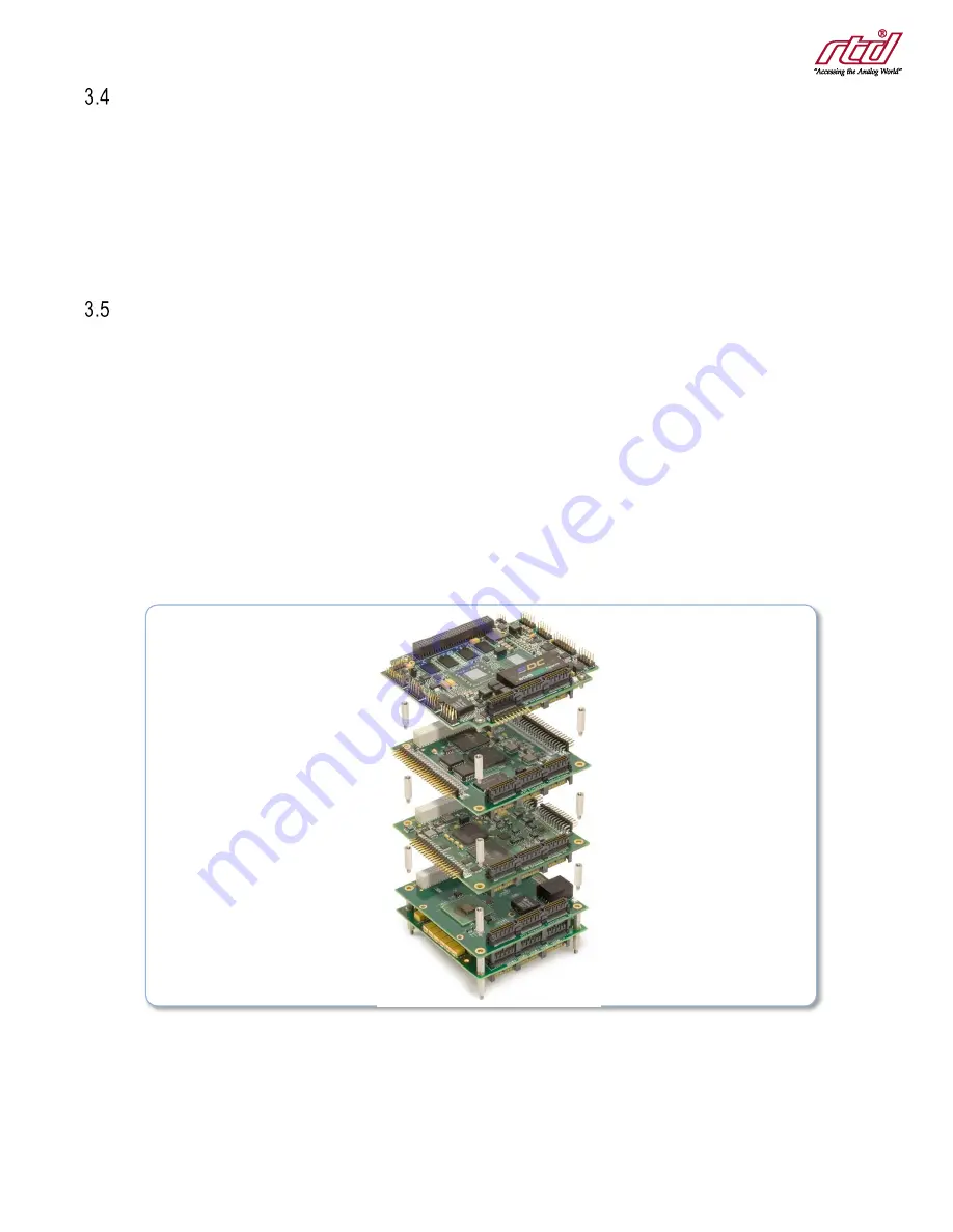
Select and install stand-offs to properly position the module on the stack.
4.
Remove the module from its anti-static bag.
5.
Check that pins of the bus connector are properly positioned.
6.
Check the stacking order; make sure all of the busses used by the peripheral cards are connected to the cpuModule.
7.
Hold the module by its edges and orient it so the bus connector pins line up with the matching connector on the stack.
8.
Gently and evenly press the module onto the PC/104 stack.
9.
If any boards are to be stacked above this module, install them.
10.
Attach any necessary cables to the PC/104 stack.
11.
Re-connect the power cord and apply power to the stack.
12.
Boot the system and verify that all of the hardware is working properly.
Figure 3: Example 104™Stack


