RTD Embedded Technologies, Inc.
| www.rtd.com
43
DM35418HR/DM35218HR
User’s Manual
BDM-610010041 Rev F
6.4.15
CH_FRONT_END_CONFIG
(M
ASKABLE
R
EAD
/W
RITE
)
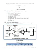
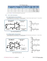
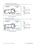
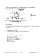
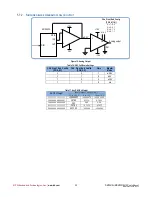
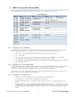
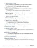
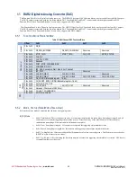
Refer to section 5.6.2 for more information about the front end circuit.
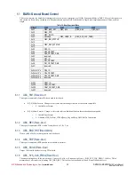
This register provides configuration to the Front End for this ADC Channel.
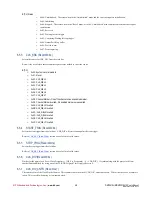
B[5]: G_05_1 – 0 = gain *0.5 selected, 1 = gain *1 selected
B[4]: PGA_A1
B[3]: PGA_A0
o
PGA_A[1:0] = 00: Gain of 1
o
PGA_A[1:0] = 01: Gain of 2
o
PGA_A[1:0] = 10: Gain of 4
o
PGA_A[1:0] = 11: Gain of 8
B[2]: BIP_UNI
0 = bipolar operation
1 = unipolar operation
B[1:0]: MODE
o
00 = input connected to +5V VREF
o
01 = single ended operation
o
11 = differential operation
6.4.16
CH
N
_FIFO_DATA_CNT
(R
EAD
)
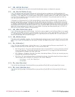
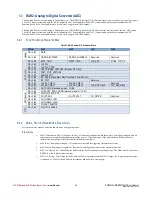
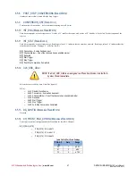
This register shows the current sample count that is available in the ADC channel FIFO.
6.4.17
CH_FILTER
(R
EAD
/W
RITE
)
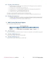
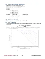
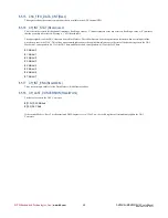
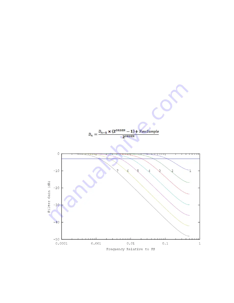
The programmable digital filter provides a single pole Infinite Impulse Response (IIR) filter on each channel. This a unity-gain filter. The filtered
data has a value of:
The response of the filter is shown in the Figure 16below. The Table below shows the -3dB cutoff for each of the filter settings. Both the figure
and the table are relative to the sample rate (f
s
).
Figure 16: Filter Response with each ORDER Value

