RTD Embedded Technologies, Inc.
| www.rtd.com
30
DM35418HR/DM35218HR
User’s Manual
BDM-610010041 Rev F
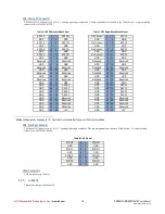
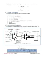
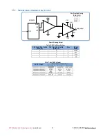
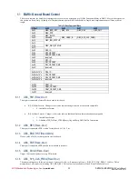
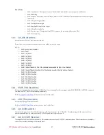
Table 15: ADC Full-Scale Settings
CHn_Front_End_Config
[PGA_A1]
CHn_Front_End_Config
[PGA_A0]
CHn_Front_End_Config
[G_05_1]
Signal
Path
Gain
Unipolar
Mode
Bipolar
Mode
0
0
1
1
0-10V
±5V
0
1
1
2
0-5V
±2.5V
1
0
1
4
0-2.5V
±1.25V
1
1
1
8
0-1.25V
±0.625V
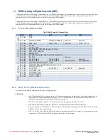
Refer to section
for more information about FPGA register control
5.6.3
I
NPUT CONNECTION EXAMPLES
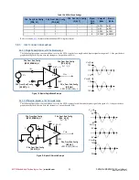
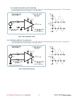
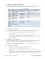
5.4.3.1. Single Ended, Bipolar, ±10V Full-scale range
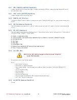
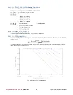
The following figure shows an example how to set up the FPGA registers for a single-ended, bipolar signal with a gain of 1. Also provided are
graphs showing the difference between the input vs. output from the PGA.
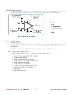
5.4.3.2. Differential, Bipolar, ±10V Full-scale range
The following figure shows an example how to set up the FPGA registers for a differential, bipolar signal with a gain of 1. Also provided are
graphs showing the difference between the inputs vs. output from the PGA.
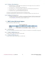
Figure 10: Bipolar Single-Ended Example
t
10V
V
in
(t)
-10V
t
10V
V
PGA
(t)
-10V
t
5V
-5V
t
5V
-5V
V
in
-
(t)
t
V
in
+
(t)
10V
V
PGA
(t)
-10V
V
in-
V
in+
+
-
VREF
+15V
-15V
IN+
IN-
A1 A0 -> G
Gain
CHn_Front_End_Config
[BIP_UNI]
VREF: 0V: [BIP_UNI] = 0
+
-
CHn_Front_End_Config
[VREF_NORMAL] = 1
CHn_Front_End_Config
[SE_DIFF] = 1
V
PGA
+
-
CHn_Front_End_Config
[PGA_A[1:0]]
G=1
:
0, 0
+
-
VREF
+15V
-15V
IN+
IN-
A1 A0 -> G
Gain
CHn_Front_End_Config
[BIP_UNI]
VREF: 0V: [BIP_UNI] = 0
X
+
-
CHn_Front_End_Config
[VREF_NORMAL] = 1
CHn_Front_End_Config
[SE_DIFF] = 0
V
in
V
PGA
CHn_Front_End_Config
[PGA_A[1:0]]
G=1
:
0, 0
Figure 11: Bipolar Differential Example

