RTD Embedded Technologies, Inc.
|
www.rtd.com
13
ERES35105
User’s Manual
3.3.2
B
US
C
ONNECTORS
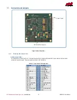
CN1 (Top) & CN2 (Bottom): PCIe Connector
The PCIe connector is the connection to the system CPU. The position and pin assignments are compliant with the
PCI/104-Express
Specification
. (See PC/104 Specifications on page 37)
The ERES35105 is a
“Universal” board, and can connect to either a Type 1 or Type 2 PCIe/104 connector.
3.3.3
J
UMPERS
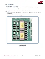
On all jumpers, pin 1 is designated by a thick white silkscreen line, and a square pad on the PCB. The jumpers are discussed in the following
sections of this manual.
The jumper settings are described in Section 6 starting on page 21.
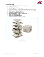
Figure 3: Jumper Locations
JP116
JP115
JP117
JP119
JP121
JP118
JP120
JP114
JP111
JP112
JP110
JP113
JP216
JP215
JP217
JP219
JP221
JP218
JP220
JP214
JP211
JP212
JP210
JP213
JP121
JP122


