

RTD Embedded Technologies, Inc.
|
www.rtd.com
22
ERES35105
User’s Manual
6.1.2
S
YNCHRO
I
NPUT
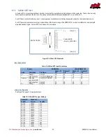
A synchro is a type of absolute rotary encoder. It consists of an excitation coil in the rotor, and three pickup coils in the stator at a 120° angles.
The pickup coils have leads that are generally labeled S1, S2, and S3. The other ends of the coils are tied together. This section described
how to connect and configure this board for use with a synchro.
A synchro also requires a reference input. Please see Section 6.2 on page 26 for information on connecting the reference.
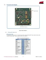
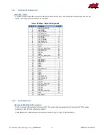
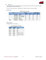
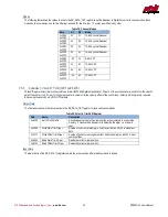
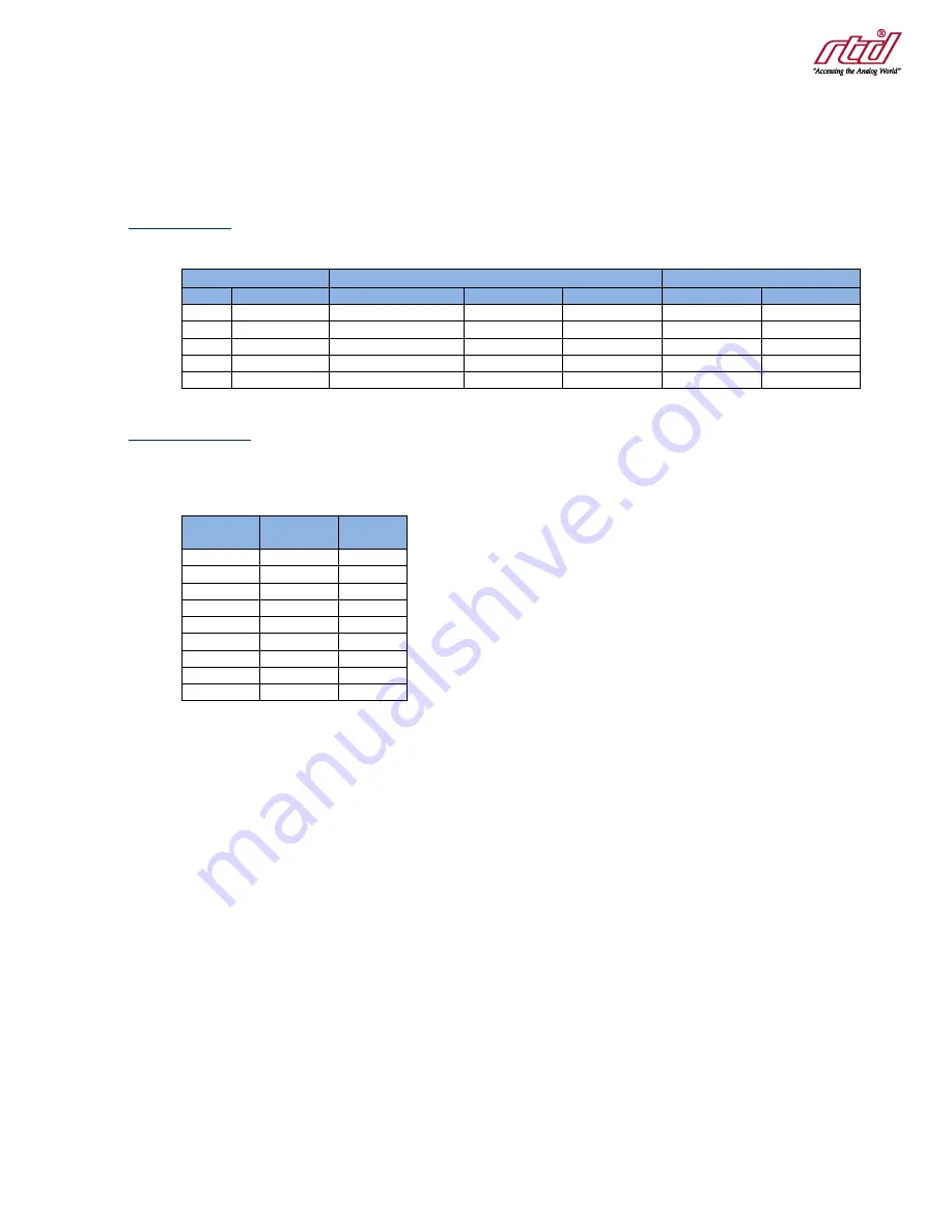
Input Connections
Table 10: Synchro Input Connections
Sensor
ERES35105
IDAN-ERES35105
Lead
Description
Pin Name
Channel 0 Pin
Channel 1 Pin
Channel 0 Pin
Channel 1 Pin
S1
240°
CHx_S1
19
27
10
14
No Connection
CHx_S2_RESOLVER
23
31
12
16
S2
0°
CHx_S2_SYNCHRO
24
32
31
35
S3
120°
CHx_S3
20
28
29
33
No Connection
CHx_S4
22
30
30
34
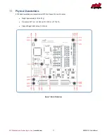
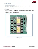
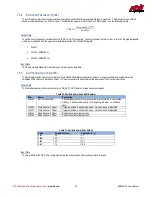
Jumper Configuration
See Figure 3 on page 13 for jumper locations.
Table 11: Synchro Jumper Settings
Channel 0
Jumper
Channel 1
Jumper
Position
JP110
JP210
2-3
JP111
JP211
2-3
JP112
JP212
2-3
JP113
JP213
2-3
JP114
JP214
2-3
JP115
JP215
1-2
JP116
JP216
1-2
JP117
JP217
1-2
JP118
JP218
1-2


