RTD Embedded Technologies, Inc.
|
www.rtd.com
23
ERES35105
User’s Manual
6.1.3
2-W
IRE
LVDT
I
NPUT
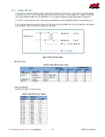
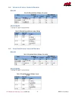
A 2-wire LVDT is a type of absolute linear encoder. It consists of an excitation coil and a pickup coil. There is also a moving ferromagnetic
core between the two coils. The output amplitude is directly proportional to the position of the ferromagnetic core. The pickup coil has leads
that are generally labeled FEEDBACK HI and FEEDBACK LO. The excitation has leads that are generally labeled REF HI and REF LO.
An LVDT does not use the reference input. It does require an excitation source that may be supplied on-board or from an external source.
An LVDT generally requires some scaling to make full use of the dynamic range of the ERES35105. In order to facilitate this, the signal path
allows the addition of gain. Contact RTD Tech Support for more details.
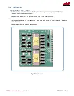
Figure 9: 2-Wire LVDT Schematic
Input Connections
Table 12: 2-Wire LVDT Input Connections
Sensor
ERES35105
IDAN-ERES35105
Lead
Description
Pin Name
Channel 0
Pin
Channel 1
Pin
Channel 0
Pin
Channel 1
Pin
FEEDBACK LO
Pickup -
CHx_S1
19
27
10
14
REF HI
Exci
CHx_S2_RESOLVER
23
31
12
16
No Connection
CHx_S2_SYNCHRO
24
32
31
35
FEEDBACK HI
CHx_S3
20
28
29
33
REF LO
Excitation -
CHx_S4
22
30
30
34
Jumper Configuration
See Figure 3 on page 13 for jumper locations.
Table 13: 2-Wire LVDT Jumper Settings
Channel 0
Jumper
Channel 1
Jumper
Position
JP110
JP210
1-2
JP111
JP211
1-2
JP112
JP212
1-2
JP113
JP213
1-2
JP114
JP214
1-2
JP115
JP215
2-3
JP116
JP216
2-3
JP117
JP217
2-3
JP118
JP218
2-3
JP119
JP219
2-3
JP120
JP220
Any
JP121
JP221
Any
JP122
JP222
1-2
EXCITATION IN
FEEDBACK HI
(CHx_S3)
FEEDBACK LO
(CHx_S1)
REF HI (CHx_S2_RESOLVER)
REF LO (CHx_S4)

