RTD Embedded Technologies, Inc.
|
www.rtd.com
26
ERES35105
User’s Manual
Reference Input
The resolver converter requires a reference input. The reference can come from the on-board excitation signal, or from an external source.
The connection to the reference is found in the following sections.
The converter uses a synthesized reference, allowing up to 45 degrees of phase shift between the reference input and the sensor inputs.
NOTE: When using in LVDT mode, the reference is derived on-board from
the input signals. The CHx_REF_IN signals must be left unconnected.
6.2.1
I
NTERNALLY
G
ENERATED
R
EFERENCE
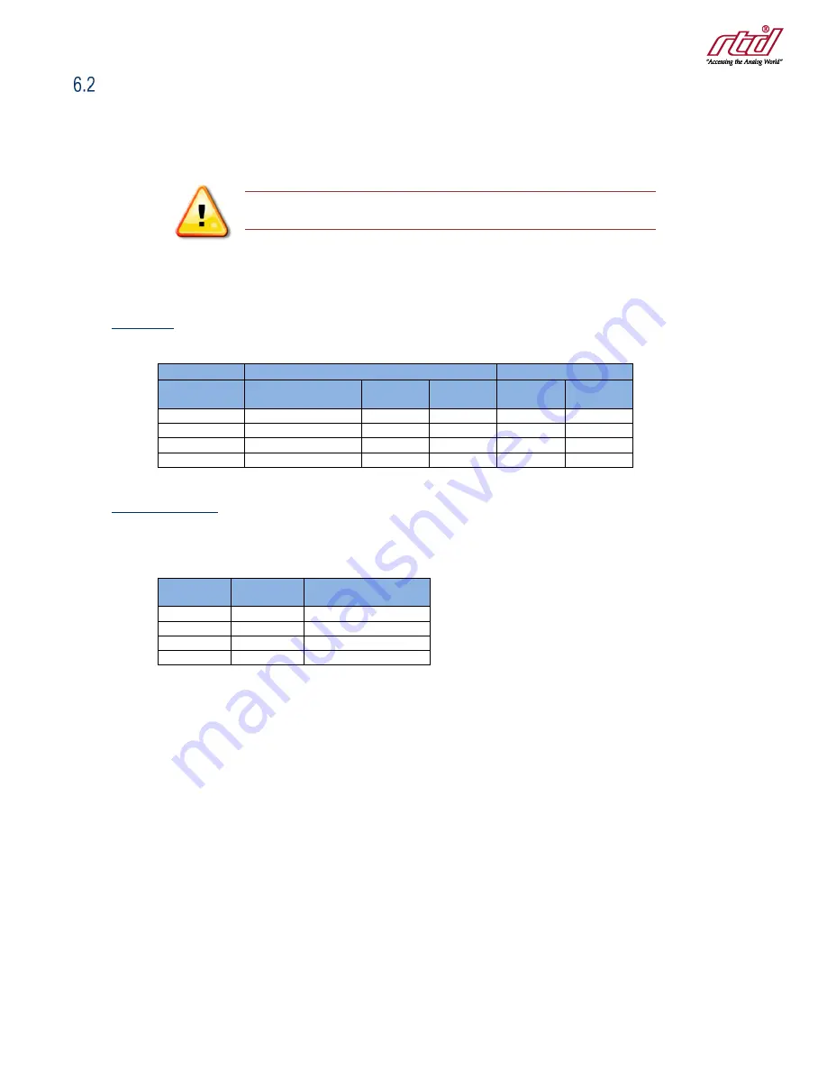
Connections
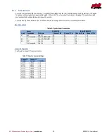
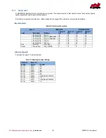
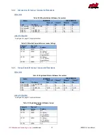
Table 18: Internal Reference Connections
Sensor
ERES35105
IDAN-ERES35105
Lead
Pin Name
Channel 0
Pin
Channel 1
Pin
Channel 0
Pin
Channel 1
Pin
REF HI
CHx_EXCITATION
1
9
1
5
REF LO
GND
2
20
22
6
No Connection
CHx
7
4
15
8
No Connection
CHx_REF_IN-
8
23
16
27
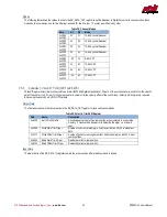
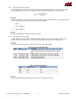
Jumper Configuration
See Figure 3 on page 13 for jumper locations.
Table 19: Internal Reference Jumper Settings
Channel 0
Jumper
Channel 1
Jumper
Position
JP119
JP219
2-3
JP120
JP220
1-2
JP121
JP221
1-2
JP122
JP222
2-3

