RTD Embedded Technologies, Inc.
|
www.rtd.com
vi
ERES35105
User’s Manual
Table of Figures
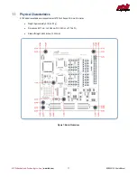
Figure 1: Board Dimensions ................................................................................................................................................................................... 11
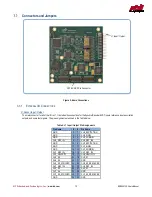
Figure 2: Board Connections .................................................................................................................................................................................. 12
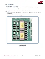
Figure 3: Jumper Locations .................................................................................................................................................................................... 13
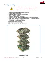
Figure 4: Example 104™Stack
............................................................................................................................................................................... 14
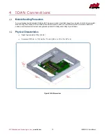
Figure 5: IDAN Dimensions .................................................................................................................................................................................... 15
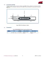
Figure 6: IDAN Front Panel Connector Locations .................................................................................................................................................. 16
Figure 7: Example IDAN System ............................................................................................................................................................................ 18
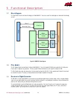
Figure 8: ERES35105 Block Diagram .................................................................................................................................................................... 19
Figure 9: 2-Wire LVDT Schematic .......................................................................................................................................................................... 23
Figure 10: 3-Wire LVDT Schematic ........................................................................................................................................................................ 24
Table of Tables
Table 1: Ordering Options ........................................................................................................................................................................................ 7
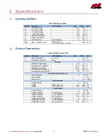
Table 2: Operating Conditions .................................................................................................................................................................................. 9
Table 3: Electrical Characteristics ............................................................................................................................................................................ 9
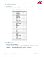
Table 4: J1 Input / Output Pin Assignments .......................................................................................................................................................... 12
Table 5: IDAN-ERES35105HR-xS Panel Connectors and Mating Connectors ..................................................................................................... 16
Table 6: IDAN Input / Output Pin Assignments ..................................................................................................................................................... 17
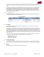
Table 7: Bandwidth Filters ...................................................................................................................................................................................... 20
Table 8: Resolver Input Connections...................................................................................................................................................................... 21
Table 9: Resolver Jumper Settings......................................................................................................................................................................... 21
Table 10: Synchro Input Connections..................................................................................................................................................................... 22
Table 11: Synchro Jumper Settings........................................................................................................................................................................ 22
Table 12: 2-Wire LVDT Input Connections ............................................................................................................................................................. 23
Table 13: 2-Wire LVDT Jumper Settings ................................................................................................................................................................ 23
Table 14: 3-Wire LVDT Input Connections ............................................................................................................................................................. 24
Table 15: 3-Wire LVDT Jumper Settings ................................................................................................................................................................ 24
Table 16: Direct Input Connections ........................................................................................................................................................................ 25
Table 17: Direct Input Jumper Settings .................................................................................................................................................................. 25
Table 18: Internal Reference Connections ............................................................................................................................................................. 26
Table 19: Internal Reference Jumper Settings ....................................................................................................................................................... 26
Table 20: Differential External Reference Connections .......................................................................................................................................... 27
Table 21: Differential External Reference Jumper Settings.................................................................................................................................... 27
Table 22: Single-Ended External Reference Connections ..................................................................................................................................... 27
Table 23: Single-Ended External Reference Jumper Settings ............................................................................................................................... 27
Table 24: Identifying the ERES35105..................................................................................................................................................................... 28
Table 25: Index and Data Registers ....................................................................................................................................................................... 28
Table 26: Board Registers ...................................................................................................................................................................................... 31
Table 27: Channel Mode Shift Register .................................................................................................................................................................. 33
Table 28: Channel Modes ....................................................................................................................................................................................... 34
Table 29: Velocity Trim Shift Register .................................................................................................................................................................... 34
Table 30: Excitation Amplitude Shift Register ........................................................................................................................................................ 35
Table 31: Excitation Amplitude Values ................................................................................................................................................................... 35


