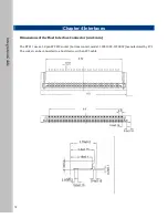
background image

In

teg

ra

tio

n

Gu

id

e

RT211
OEM Scan Engine

Integration Guide

Summary of Contents for RT211

Page 1: ...Integration Guide RT211 OEM Scan Engine Integration Guide ...

Page 2: ...lation Orientation 3 Optics 3 Window Placement 3 Window Material and Color 4 Scratch Resistance and Coating 4 Window Size 4 Ambient Light 6 Eye Safety 6 Mounting 7 Front View unit mm 7 Side View unit mm 7 Top View unit mm 8 Chapter 3 Electrical Specifications 9 Power Supply 9 Ripple Noise 9 DC Characteristics 9 Operating Voltage 9 Operating Current 9 Power sequencing 10 Chapter 4 Interfaces 11 ...

Page 3: ...rface Connector 11 Dimensions of the Host Interface Connector unit mm 12 FFC Cable unit mm 13 Communication Interfaces 14 Control Interfaces 15 Reset 15 Trigger 15 Beeper 16 Good Read LED 17 Chapter 5 Development Tools 18 EVK 18 ...

Page 4: ...gies 1D EAN 13 EAN 8 UPC A UPC E ISSN ISBN Codabar Code 128 including FNC1 FNC2 and FNC3 Code 93 ITF 6 ITF 14 Interleaved 2 of 5 Industrial 2 of 5 Standard 2 of 5 Matrix 2 of 5 GS1 Databar RSS Expand RSS Limited RSS 14 Code 39 Code 11 MSI Plessey Plessey 2D PDF 417 QR Code QR1 QR2 Micro QR Data Matrix Chinese Sensible Code T M Illumination The RT211 has a white LED for supplementary lighting The i...

Page 5: ...nd circuit board Dust and other external contaminants will eventually degrade the engine s performance Thermal Considerations Electronic components in the RT211 will generate heat during the course of their operation Operating the RT211 in continuous mode for an extended period may cause temperatures to rise on CIS and decoder chip Overheating can degrade image quality and affect scanning performa...

Page 6: ...ions can degrade the reading performance The window should be mounted close to the front of the engine parallel The maximum distance is measured from the front of the engine housing to the farthest surface of the window In order to reach better reading performance the distance from the front of the engine housing to the furthest surface of the window should not exceed 2mm and the distance from the...

Page 7: ...ggested to use PMMA or optical glass with spectral transmittance over 90 and haze less than 1 Whether to use an anti reflection coating or not depends on the material and application needs Scratch Resistance and Coating Scratch on the window can greatly reduce engine performance It is suggested to use abrasion resistant window material or coating Window Size The window must not block the field of ...

Page 8: ...5 Integration Guide Vertical ...

Page 9: ...0 60Hz AC power However high frequency pulsed light can result in performance degradation Eye Safety The RT211 uses LEDs to create the aiming and illumination beams The LEDs are bright but testing has been done to demonstrate that the engine is safe for its intended application under normal usage conditions However the user should avoid looking into the beam ...

Page 10: ...ntegration Guide Mounting The illustrations below show the mechanical mounting dimensions for the RT211 The structural design should leave some space between components Front View unit mm Side View unit mm ...

Page 11: ...8 Integration Guide Top View unit mm ...

Page 12: ... cutting it off The minimum interval must exceed 2 seconds Ripple Noise Image sensor and decoder chip are directly fed by the input power of RT211 To ensure the image quality a power supply with low ripple noise is needed Acceptable ripple range peak to peak 50mV 30mV recommended DC Characteristics Operating Voltage Ta 23 Parameter Description Minimu m Typical Maximum Unit VDD Voltage Drain Drain ...

Page 13: ...pletion time is about 400ms 2 In the above picture D is the reset time If there is no additional operation on the Reset signal during power on the system boot time starts when VDD reaches 3 3V 3 When powering off make sure that all communication interface data is transmitted and then powered off to avoid transmission errors 4 The level of other signals must be kept low before VDD is powered on to ...

Page 14: ...USB D differential data signal optional 7 USB_D I O USB D differential data signal optional 8 NC Not connected 9 Buzz O Beeper output For the information of beeper driver circuit see the Beeper section in this chapter 10 LED O Good Read LED output For the information of LED driver circuit see the Good Read LED section 11 Reset I Reset signal input Active low Driving this pin low for 100us 500us re...

Page 15: ...ntegration Guide Dimensions of the Host Interface Connector unit mm The RT211 uses a 12 pin FPC ZIF socket bottom contact model 10051922 1210ELF manufactured by FCI The socket can be connected to a host device with an FFC cable ...

Page 16: ...n FFC cable can be used to connect the RT211 to a host device The cable design must be consistent with the specifications shown below Use reinforcement material for the connectors on the cable and reduce cable impedance for reliable connection and stable performance ...

Page 17: ...B HID Keyboard Based on USB connection the engine s transmission is simulated as USB keyboard input It works on a Plug and Play basis and no driver is required USB COM Port Emulation The USB port on the host device is emulated as a serial port with the same data transmission and configuration as a real serial port A driver is required HID POS optional HID POS does not require a custom driver Howev...

Page 18: ...to start a scan and decode session If barcode is decoded the RT211 waits for the voltage at the nTrig pin to turn high or the trigger to be released after sending the data to the Host If the trigger is released during a scan attempt the RT211 immediately stops decoding Next decode session does not happen until the RT211 receives active trigger signal driving thenTrig pin low again As a decode sess...

Page 19: ...at provides a PWM output to an external driver circuit for generating audible feedback to the user to indicate statuses like power up or good read The PWM output is not strong enough to drive a beeper thus a beeper driver circuit is needed The following beeper driver circuit is provided for reference D 2 B A T 7 6 0 ...

Page 20: ...ernal driver circuit to drive an LED to indicate a Good Read status When a good read occurs the LED pin produces a high level output for about 300ms and then the signal is back to a low level This Good Read LED output is not strong enough to drive an LED so an LED driver circuit is needed The following LED driver circuit is provided for reference ...

Page 21: ...USB converter RS 232 USB interfaces etc The RT211 can be connected to the EVK via a 12 pin FFC cable type 1 contacts on the same side Either USB connection or RS 232 connection can be used when connecting the EVK to a host device RTSCAN TECHNOLOGY LIMITED Add 410 Building 10 Cloud valley Phase II Pingshan 1st Road Xili Nanshan Shenzhen 518055 China Tel 86 0 755 23762089 Email info rtscan net Web w...

Reviews: