RT
21
4
In
te
gr
ati
on
gu
id
e
19
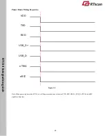
1. In the diagram above, it takes
A+B+C
(about 215ms) for the engine to power up:
A
is bootloader execution time
(25ms),
B
is kernel boot time (5ms) and
C
is decoding chip initialization time(185ms).
2. D is reset time (300us). If the Reset signal is not operated when powered on, the startup time should be calculated
after VCC_3V3 reaches 3.3V.
3. Ensure that all communication interface data has been transmitted before powering off.
4.
The RT214 has a 100K pull-up on the nTRIG signal. During the period between power-on and bootloader execution,
the user should not lower the nTRIG signal. If nTRIG is set high before power-on, it should meet the duration of E
(E=0~1ms) as shown in Figure 3-4. Levels of other signals are kept low during power-on to prevent abnormal function.
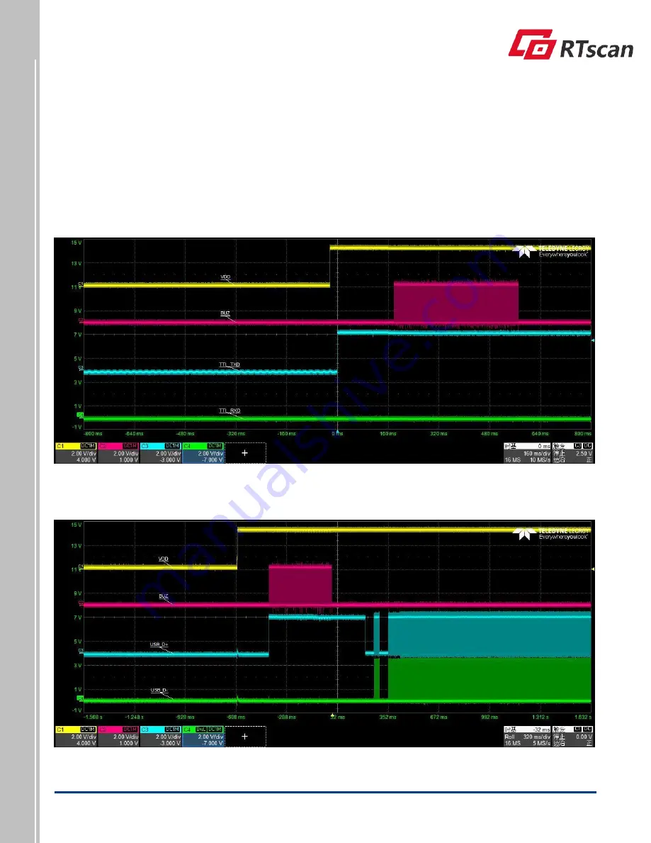
Power Up Timing Sequence (Serial Interface) Figure 3-6
Power Up Timing Sequence(USB) Figure 3-7


