Peakmeter series 1252
Getting started Page 5-3
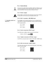
5.4. Connections
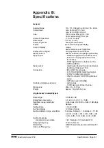
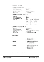
The series 1252 peakmeter feature AES/EBU, SPDIF and OPTICAL inputs
as well as a signal output. We recommend that the screen of the XLR AF
line is connected to the source end only to avoid ground loops.
5.4.1. Power supply
Supply voltage is connected to the built-in mains connector type IEC 320/
C18 by means of the mains power cable supplied with the unit.
5.4.2. XLR-f connector: AES/EBU input
The AES/EBU input is transformer balanced. The units integrated termi-
nating resistor is activated or deactivated by setting a jumper accordingly.
XLR-f is wired as follows:
Pin 1 - screen
Pin 2 - hot (+)
Pin 3 - cold ()
5.4.3. Cinch connector: SPDIF input
The SPDIF input is unbalanced and internally 75 W terminated.
Center pin - SPDIF in
5.4.4. Toslink connector: OPTICAL input
The OPTICAL input uses receiver circuits from TOSHIBA, TOSLINK series.
5.4.5. XLR-m connector: signal output
The signal output is transformer balanced and internally 110
Ω
terminated.
XLR-m is wired as follows:
Pin 1 - screen
Pin 2 - hot (+)
Pin 3 - cold ()
Terminating resistor see
section 6.5.1..
2
1
3
1
2
3

