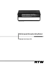
Peakmeter Serie 1252
Über diese Anleitung/Scope of this manual Seite/Page iii
Inhaltsverzeichnis
1.
Einführung ......................................................................1-1
2.
Erste Schritte ..................................................................2-1
2.1. Inbetriebnahme ..........................................................2-1
2.1.1. Spannungswahl ......................................................2-1
2.2. Sicherheits-Symbole ..................................................2-2
2.3. Sicherheitshinweise ...................................................2-2
2.4. Anschlüsse ................................................................2-3
2.4.1. Stromversorgung ....................................................2-3
2.4.2. XLR-f-Anschluss: AES/EBU-Eingang .....................2-3
2.4.3. Cinch-Anschluss: SPDIF-Eingang ..........................2-3
2.4.4. Toslink-Anschluss: Optischer Eingang....................2-3
2.4.5. XLR-m-Anschluss: Signal-Ausgang ........................2-4
2.5. Schiebeskala..............................................................2-4
3.
Bedienungshinweise .....................................................3-1
3.1. Anzeige-Charakteristiken ...........................................3-1
3.2. Over-Anzeigen ...........................................................3-2
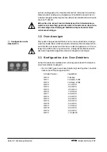
3.3. Konfiguration des Over-Detektors..............................3-2
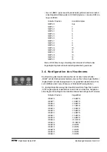
3.4. Konfiguration des Headrooms....................................3-3
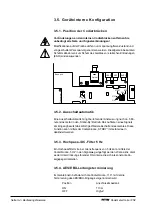
3.5. Geräteinterne Konfiguration .......................................3-4
3.5.1. Position der Codierbrücken .....................................3-4
3.5.2. Ausschaltautomatik .................................................3-4
3.5.2. Hochpass-/DC-Filter 5 Hz .......................................3-4
3.5.4. AES/EBU-Leitungsterminierung ..............................3-4
4.
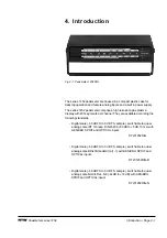
Introduction .....................................................................4-1
5.
Getting started................................................................5-1
5.1. First time operation. ...................................................5-1
5.1.1. Changing line voltage selection ...............................5-1
5.2. Safety symbols. .........................................................5-2
5.3. Safety information. .....................................................5-2
5.4. Connections ...............................................................5-3
5.4.1. Power supply ..........................................................5-3
5.4.2. XLR-f connector: AES/EBU input ............................5-3
5.4.3. Cinch connector: SPDIF input.................................5-3
5.4.4. Toslink connector: OPTICAL input ..........................5-3
5.4.5. XLR-m connector: signal output..............................5-3
5.5. Switchable scale ........................................................5-4

