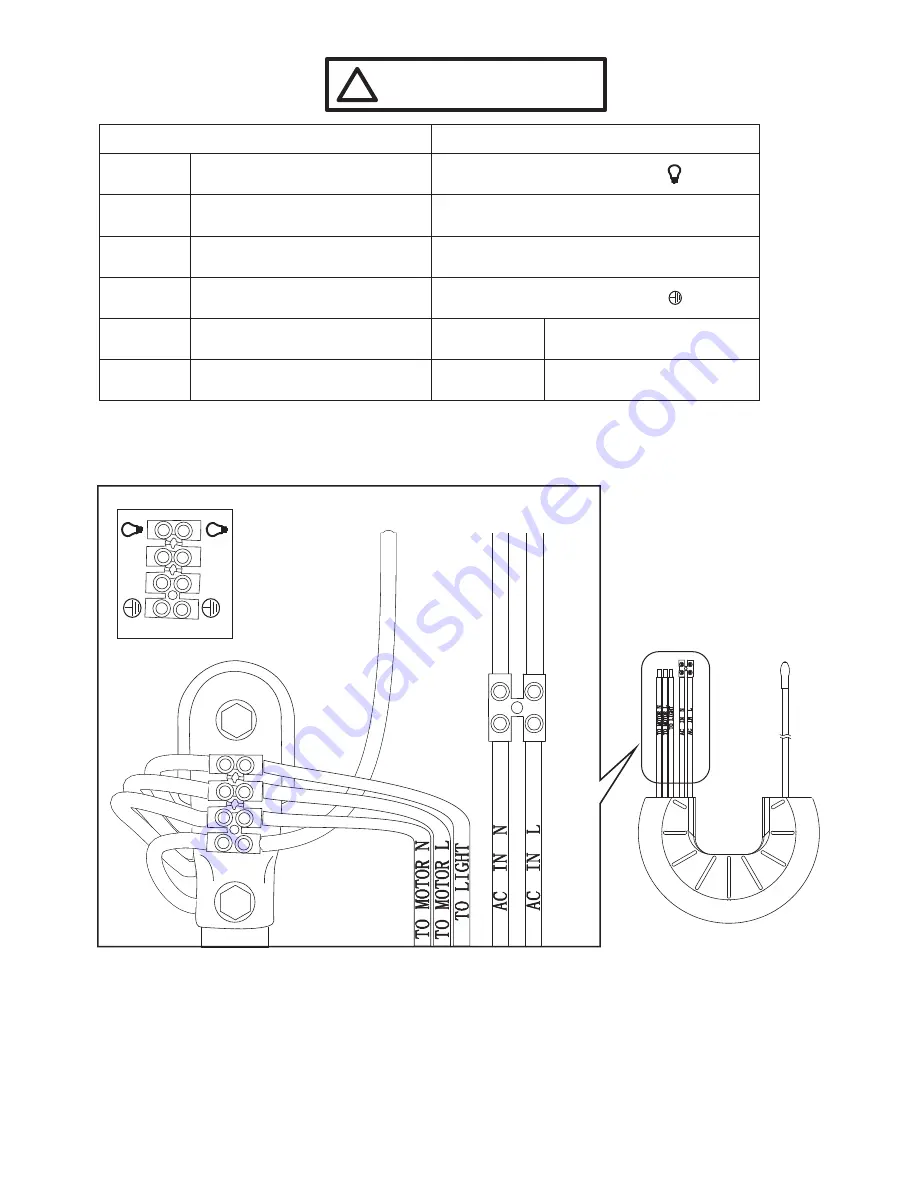
DIAGRAM 5
SUPPLY CIRCUIT
Receiver
E
A
R
T
H
w
ir
e
(G
re
e
n
)
N
E
U
T
R
A
L
w
ir
e
(B
la
c
k
/
B
lu
e
)
L
IV
E
w
ir
e
(R
e
d
/
B
ro
w
n
)
Page 5
STEP 5 (See Diagram 5)
Ceiling
Ceiling
Ceiling
Receiver
Receiver
Receiver
Blue Wire
(TO MOTOR N)
Red / Brown Wire
(Incoming LIVE Wire)
Black / Blue Wire
(Incoming NEUTRAL Wire)
Green Wire
(Incoming EARTH Wire)
Red Wire (AC in L)
Black Wire (AC in N)
Terminal Block (marked
)
“N”
Receiver
Brown Wire
(TO MOTOR L)
Terminal Block (marked
)
“L”
!
Connect the Motor Wiring
to Receiver first!
Connect wiring as below:-
Receiver
Orange Wire
(FOR LIGHT)
Terminal Block (marked
)
“
”
FROM
TO
F
ro
m
C
e
ili
n
g
F
ro
m
C
e
ili
n
g
F
ro
m
C
e
ili
n
g
L
N
L
N
Terminal Block (marked
)
“
”


