139
3-9. IP MAC Binding
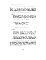
The IP network layer uses a four-byte address. The Ethernet link layer uses
a six-byte MAC address. Binding these two address types together allows the
transmission of data between the layers. The primary purpose of IP-MAC binding is
to restrict the access to a switch to a number of authorized users. Only the
authorized client can access the Switch’s port by checking the pair of IP-MAC
Addresses and port number with the pre-configured database. If an unauthorized
user tries to access an IP-MAC binding enabled port, the system will block the
access by dropping its packet.
Function name:
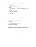
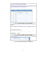
IP MAC Binding Configuration
Function description:
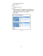
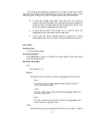
The switch has client and server two classes of IP-MAC Binding table. The
maximum number of IP-MAC binding client table is 512 entries. The maximum
number of IP-MAC Binding server table is 64 entries. The creation of authorized
users can be manually. The function is global, this means a user can enable or
disable the function for all ports on the switch.
Parameters description:
State:
Disabled / Enabled
Time Interval:
Range: 10 / 20 / 30
Time interval is for ARP echo, the switch will according to server table
entries to send ARP echo.
Server/Client:
The maximum number of IP-MAC binding client table is 512 entries. The
maximum number of IP-MAC Binding server table is 64 entries.
MAC:
Six-byte MAC Address: xx-xx-xx-xx-xx-xx
For example: 00-40-c7-00-00-01
IP:
Four-byte IP Address: xxx.xxx.xxx.xxx
For example: 192.168.1.100
Port No:
Port no.: 1-24
VID:
VLAN ID: 1-4094
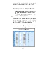
Add:
Input MAC, IP, Port and VID, then click on <Add> to create a new entry
into the IP MAC Binding table
Summary of Contents for GS-2224L
Page 1: ......
Page 2: ......
Page 34: ...24 Fig 2 15 Office Network Connection Fig 2 14 Peer to peer Network Connection ...
Page 78: ...68 Fig 3 28 ...
Page 83: ...73 Fig 3 31 ...
Page 91: ...81 Fig 3 39 Fig 3 40 Fig 3 41 ...
Page 113: ...103 Fig 3 67 Ingress Port Fig 3 68 ...
Page 115: ...105 Fig 3 71 Fig 3 72 Fig 3 73 ARP Fig 3 74 ARP ...
Page 116: ...106 Fig 3 75 ARP Fig 3 76 ARP Fig 3 77 ARP Fig 3 78 ARP ...
Page 117: ...107 Fig 3 79 ARP Fig 3 80 ARP Fig 3 81 ARP Fig 3 82 ARP ...
Page 118: ...108 Fig 3 83 ARP Fig 3 84 ARP Fig 3 85 ARP Fig 3 86 ARP Fig 3 87 ARP ...
Page 119: ...109 Fig 3 88 IPv4 Fig 3 89 IPv4 Fig 3 90 IPv4 ...
Page 120: ...110 Fig 3 91 IPv4 Fig 3 92 IPv4 Fig 3 93 IPv4 Fig 3 94 IPv4 Fig 3 95 IPv4 ...
Page 121: ...111 Fig 3 96 IPv4 Fig 3 97 IPv4 Fig 3 98 IPv4 Fig 3 99 IPv4 Fig 3 100 IPv4 ...
Page 122: ...112 Fig 3 101 IPv4 Fig 3 102 IPv4 Fig 3 103 IPv4 Fig 3 104 IPv4 ...
Page 123: ...113 Fig 3 105 IPv4 Fig 3 106 IPv4 Fig 3 107 IPv4 ...
Page 124: ...114 Fig 3 108 IPv4 Fig 3 109 IPv4 Fig 3 110 IPv4 Fig 3 111 IPv4 ...
Page 125: ...115 Fig 3 112 IPv4 Fig 3 113 IPv4 Fig 3 114 IPv4 ...
Page 126: ...116 Fig 3 115 IPv4 Fig 3 116 IPv4 Fig 3 117 IPv4 ...
Page 127: ...117 Fig 3 118 Action Fig 3 119 Rate Limiter ...
Page 128: ...118 Fig 3 120 Port Copy Fig 3 121 DMAC Filter ...
Page 129: ...119 Fig 3 122 VLAN ID Filter Fig 3 123 VLAN ID Filter Fig 3 124 Tag Priority ...
Page 141: ...131 Fig 3 126 Set up Policy Rules Fig 3 127 Set up Policy Rules Fig 3 128 Set up Policy Rules ...
Page 143: ...133 Fig 3 132 Set up Port Policies Fig 3 133 Set up Port Policies Finish ...
Page 159: ...149 Fig 3 145 ...
Page 204: ...194 Fig 4 1 Fig 4 2 ...

