159
3-12-2. Configuration
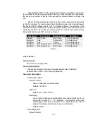
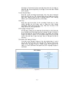
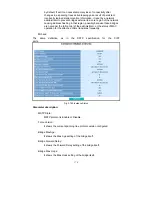
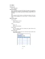
The STP, Spanning Tree Protocol, actually includes RSTP. In the Spanning
Tree Configuration, there are six
parameters open for the user to configure as
user’s idea. Each parameter description is listed below.
Function name:
STP Configuration
Function description:
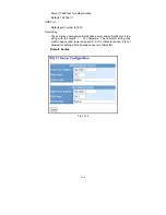
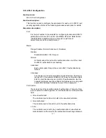
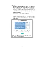
User can set the following Spanning Tree parameters to control STP function
enable/disable, select mode RSTP/STP and affect STP state machine
behavior to send BPDU in this switch. The default setting of Spanning Tree
Protocol is “Disable”.
Parameter description:
Spanning Tree Protocol:
Set 802.1W Rapid STP function Enable / Disable. Default is “Disable”
Bridge Priority:
The lower the bridge priority is, the higher priority it has. Usually, the
bridge with the highest bridge priority is the root. If you want to have the
GS-2224L as root bridge, you can set this value lower than that of bridge
in the LAN. The valid value is 0 ~ 61440. The default is 32768.
Hello Time:
Hello Time is used to determine the periodic time to send normal BPDU
from designated ports among bridges. It decides how long a bridge
should send this message to other bridge to tell I am alive. When the
GS-2224L is the root bridge of the LAN, for example, all other bridges will
use the hello time assigned by this switch to communicate with each
other. The valid value is 1 ~ 10 in unit of second.
Default is 2 seconds.
Max. Age:
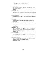
When the GS-2224L is the root bridge, the whole LAN will apply this
figure set by this switch as their maximum age time. When a bridge
received a BPDU originated from the root bridge and if the message age
conveyed in the BPDU exceeds the Max. Age of the root bridge, the
bridge will treat the root bridge malfunctioned and issue a Topology
Change Notification (TCN) BPDU to all other bridges. All bridges in the
LAN will re-calculate and determine who the root bridge is. The valid
value of Max. Age is 6 ~ 40 seconds. Default is 20 seconds.
Summary of Contents for GS-2224L
Page 1: ......
Page 2: ......
Page 34: ...24 Fig 2 15 Office Network Connection Fig 2 14 Peer to peer Network Connection ...
Page 78: ...68 Fig 3 28 ...
Page 83: ...73 Fig 3 31 ...
Page 91: ...81 Fig 3 39 Fig 3 40 Fig 3 41 ...
Page 113: ...103 Fig 3 67 Ingress Port Fig 3 68 ...
Page 115: ...105 Fig 3 71 Fig 3 72 Fig 3 73 ARP Fig 3 74 ARP ...
Page 116: ...106 Fig 3 75 ARP Fig 3 76 ARP Fig 3 77 ARP Fig 3 78 ARP ...
Page 117: ...107 Fig 3 79 ARP Fig 3 80 ARP Fig 3 81 ARP Fig 3 82 ARP ...
Page 118: ...108 Fig 3 83 ARP Fig 3 84 ARP Fig 3 85 ARP Fig 3 86 ARP Fig 3 87 ARP ...
Page 119: ...109 Fig 3 88 IPv4 Fig 3 89 IPv4 Fig 3 90 IPv4 ...
Page 120: ...110 Fig 3 91 IPv4 Fig 3 92 IPv4 Fig 3 93 IPv4 Fig 3 94 IPv4 Fig 3 95 IPv4 ...
Page 121: ...111 Fig 3 96 IPv4 Fig 3 97 IPv4 Fig 3 98 IPv4 Fig 3 99 IPv4 Fig 3 100 IPv4 ...
Page 122: ...112 Fig 3 101 IPv4 Fig 3 102 IPv4 Fig 3 103 IPv4 Fig 3 104 IPv4 ...
Page 123: ...113 Fig 3 105 IPv4 Fig 3 106 IPv4 Fig 3 107 IPv4 ...
Page 124: ...114 Fig 3 108 IPv4 Fig 3 109 IPv4 Fig 3 110 IPv4 Fig 3 111 IPv4 ...
Page 125: ...115 Fig 3 112 IPv4 Fig 3 113 IPv4 Fig 3 114 IPv4 ...
Page 126: ...116 Fig 3 115 IPv4 Fig 3 116 IPv4 Fig 3 117 IPv4 ...
Page 127: ...117 Fig 3 118 Action Fig 3 119 Rate Limiter ...
Page 128: ...118 Fig 3 120 Port Copy Fig 3 121 DMAC Filter ...
Page 129: ...119 Fig 3 122 VLAN ID Filter Fig 3 123 VLAN ID Filter Fig 3 124 Tag Priority ...
Page 141: ...131 Fig 3 126 Set up Policy Rules Fig 3 127 Set up Policy Rules Fig 3 128 Set up Policy Rules ...
Page 143: ...133 Fig 3 132 Set up Port Policies Fig 3 133 Set up Port Policies Finish ...
Page 159: ...149 Fig 3 145 ...
Page 204: ...194 Fig 4 1 Fig 4 2 ...

