161
3-12-3. STP Port Configuration
Function name:
STP Port Setting
Function description:
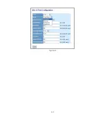
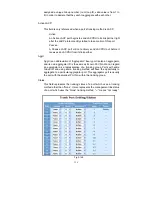
In the STP Port Setting, one item selection and five
parameters settings are
offered for user’s setup. User can disable and enable each port by selecting
each Port Status item. User also can set “Path Cost” and “Priority” of each port
by filling in the desired value and set “Admin Edge Port” and “Admin Point To
Point” by selecting the desired item.
Parameter description:
Port Status:
It displays the current state of a port. We cannot manually set it because
it displays the status only. There are three possible states. ( according to
802.1w specification)
DISCARDING state indicates that this port can neither forward packets
nor contribute learning knowledge.
Notice: Three other states (Disable state, BLOCKING state and LISTENING
state) defined in the 802.1d specification are now all represented as
DISCARDING state.
LEARNING state indicates this port can now contribute its learning
knowledge but cannot forward packets still.
FORWARDING state indicates this port can both contribute its learning
knowledge and forward packets normally.
Path Cost Status:
It is the contribution value of the path through this port to Root Bridge.
STP algorithm determines a best path to Root Bridge by calculating the
sum of path cost contributed by all ports on this path. A port with a
smaller path cost value would become the Root Port more possibly.
Configured Path Cost:
The range is 0 – 200,000,000. In the switch, if path cost is set to be zero,
the STP will get the recommended value resulted from auto-negotiation
of the link accordingly and display this value in the field of Path Cost
Status. Otherwise, it may show the value that the administrator set up in
Configured Path Cost and Path Cost Status.
Summary of Contents for GS-2224L
Page 1: ......
Page 2: ......
Page 34: ...24 Fig 2 15 Office Network Connection Fig 2 14 Peer to peer Network Connection ...
Page 78: ...68 Fig 3 28 ...
Page 83: ...73 Fig 3 31 ...
Page 91: ...81 Fig 3 39 Fig 3 40 Fig 3 41 ...
Page 113: ...103 Fig 3 67 Ingress Port Fig 3 68 ...
Page 115: ...105 Fig 3 71 Fig 3 72 Fig 3 73 ARP Fig 3 74 ARP ...
Page 116: ...106 Fig 3 75 ARP Fig 3 76 ARP Fig 3 77 ARP Fig 3 78 ARP ...
Page 117: ...107 Fig 3 79 ARP Fig 3 80 ARP Fig 3 81 ARP Fig 3 82 ARP ...
Page 118: ...108 Fig 3 83 ARP Fig 3 84 ARP Fig 3 85 ARP Fig 3 86 ARP Fig 3 87 ARP ...
Page 119: ...109 Fig 3 88 IPv4 Fig 3 89 IPv4 Fig 3 90 IPv4 ...
Page 120: ...110 Fig 3 91 IPv4 Fig 3 92 IPv4 Fig 3 93 IPv4 Fig 3 94 IPv4 Fig 3 95 IPv4 ...
Page 121: ...111 Fig 3 96 IPv4 Fig 3 97 IPv4 Fig 3 98 IPv4 Fig 3 99 IPv4 Fig 3 100 IPv4 ...
Page 122: ...112 Fig 3 101 IPv4 Fig 3 102 IPv4 Fig 3 103 IPv4 Fig 3 104 IPv4 ...
Page 123: ...113 Fig 3 105 IPv4 Fig 3 106 IPv4 Fig 3 107 IPv4 ...
Page 124: ...114 Fig 3 108 IPv4 Fig 3 109 IPv4 Fig 3 110 IPv4 Fig 3 111 IPv4 ...
Page 125: ...115 Fig 3 112 IPv4 Fig 3 113 IPv4 Fig 3 114 IPv4 ...
Page 126: ...116 Fig 3 115 IPv4 Fig 3 116 IPv4 Fig 3 117 IPv4 ...
Page 127: ...117 Fig 3 118 Action Fig 3 119 Rate Limiter ...
Page 128: ...118 Fig 3 120 Port Copy Fig 3 121 DMAC Filter ...
Page 129: ...119 Fig 3 122 VLAN ID Filter Fig 3 123 VLAN ID Filter Fig 3 124 Tag Priority ...
Page 141: ...131 Fig 3 126 Set up Policy Rules Fig 3 127 Set up Policy Rules Fig 3 128 Set up Policy Rules ...
Page 143: ...133 Fig 3 132 Set up Port Policies Fig 3 133 Set up Port Policies Finish ...
Page 159: ...149 Fig 3 145 ...
Page 204: ...194 Fig 4 1 Fig 4 2 ...

