176
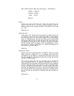
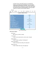
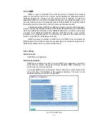
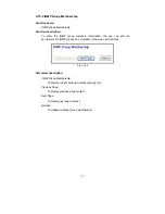
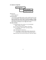
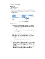
Parameter description:
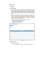
IGMP Proxy Enable:
The function supports to enable the IGMP Proxy on Switch.
Enable:
To evoke the ” IGMP Proxy Enable” to enable IGMP Proxy on
Switch.
Default: Disable
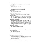
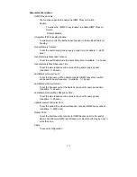
Unregister IPMC Flooding Enable:
To enable to control the traffic doesn’t appear in the multicast table for
flooding
General Query Interval: :
To set the switch send general query period time. (Available : 1~3600
secs)
General Query Response Timeout :
To set the switch determine the client living time. (Available : 1~25 secs)
General Query Max Response Time :
To set the max response code value of the general query packet .
(Available : 1~25 secs)
Last Member Query Count :
To set the frequency. When Switch received IGMP leave then switch
send specific query frequency. (Available : 1~16 secs)
Last Member Query Interval :
To set the frequency what the Switch send specific query period time.
(Available : 1~25 secs)
Last Member Query Max Response Time :
To set the max response code value in the specific query packet
(Available : 1~25 secs)
Update Interval of Router Port :
To set the period time what interface ever received IGMP query packet.
(Available : 1~3600 secs)
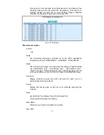
Router Ports:
To set the interface what connect to IGMP Router, and it is the switch
what it send/receive IGMP report/leave port. Router ports may be only or
more than one.
Apply:
To save all configuration.
Summary of Contents for GS-2224L
Page 1: ......
Page 2: ......
Page 34: ...24 Fig 2 15 Office Network Connection Fig 2 14 Peer to peer Network Connection ...
Page 78: ...68 Fig 3 28 ...
Page 83: ...73 Fig 3 31 ...
Page 91: ...81 Fig 3 39 Fig 3 40 Fig 3 41 ...
Page 113: ...103 Fig 3 67 Ingress Port Fig 3 68 ...
Page 115: ...105 Fig 3 71 Fig 3 72 Fig 3 73 ARP Fig 3 74 ARP ...
Page 116: ...106 Fig 3 75 ARP Fig 3 76 ARP Fig 3 77 ARP Fig 3 78 ARP ...
Page 117: ...107 Fig 3 79 ARP Fig 3 80 ARP Fig 3 81 ARP Fig 3 82 ARP ...
Page 118: ...108 Fig 3 83 ARP Fig 3 84 ARP Fig 3 85 ARP Fig 3 86 ARP Fig 3 87 ARP ...
Page 119: ...109 Fig 3 88 IPv4 Fig 3 89 IPv4 Fig 3 90 IPv4 ...
Page 120: ...110 Fig 3 91 IPv4 Fig 3 92 IPv4 Fig 3 93 IPv4 Fig 3 94 IPv4 Fig 3 95 IPv4 ...
Page 121: ...111 Fig 3 96 IPv4 Fig 3 97 IPv4 Fig 3 98 IPv4 Fig 3 99 IPv4 Fig 3 100 IPv4 ...
Page 122: ...112 Fig 3 101 IPv4 Fig 3 102 IPv4 Fig 3 103 IPv4 Fig 3 104 IPv4 ...
Page 123: ...113 Fig 3 105 IPv4 Fig 3 106 IPv4 Fig 3 107 IPv4 ...
Page 124: ...114 Fig 3 108 IPv4 Fig 3 109 IPv4 Fig 3 110 IPv4 Fig 3 111 IPv4 ...
Page 125: ...115 Fig 3 112 IPv4 Fig 3 113 IPv4 Fig 3 114 IPv4 ...
Page 126: ...116 Fig 3 115 IPv4 Fig 3 116 IPv4 Fig 3 117 IPv4 ...
Page 127: ...117 Fig 3 118 Action Fig 3 119 Rate Limiter ...
Page 128: ...118 Fig 3 120 Port Copy Fig 3 121 DMAC Filter ...
Page 129: ...119 Fig 3 122 VLAN ID Filter Fig 3 123 VLAN ID Filter Fig 3 124 Tag Priority ...
Page 141: ...131 Fig 3 126 Set up Policy Rules Fig 3 127 Set up Policy Rules Fig 3 128 Set up Policy Rules ...
Page 143: ...133 Fig 3 132 Set up Port Policies Fig 3 133 Set up Port Policies Finish ...
Page 159: ...149 Fig 3 145 ...
Page 204: ...194 Fig 4 1 Fig 4 2 ...

