12
2-1-2. Installing Chassis to a 19-Inch Wiring Closet Rail
Caution: Allow a proper spacing and proper air ventilation for the cooling fan
at both sides of the chassis.
⇒
Wear a grounding device for electrostatic discharge.
⇒
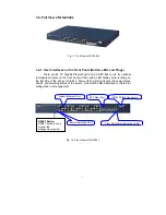
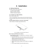
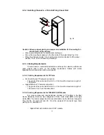
Screw the mounting accessory to the front side of the switch (See Fig. 2-2).
⇒
Place the Chassis into the 19-inch wiring closet rail and locate it at the proper
position. Then, fix the Chassis by screwing it.
2-1-3. Cabling Requirements
To help ensure a successful installation and keep the network performance
good, please take a care on the cabling requirement. Cables with worse
specification will render the LAN to work poorly.
2-1-3-1. Cabling Requirements for TP Ports
⇒
For Fast Ethernet TP network connection
⎯
The grade of the cable must be Cat. 5 or Cat. 5e with a maximum length of
100 meters.
⇒
Gigabit Ethernet TP network connection
⎯
The grade of the cable must be Cat. 5 or Cat. 5e with a maximum length of
100 meters. Cat. 5e is recommended.
2-1-3-2. Cabling Requirements for 1000SX/LX SFP Module
It is more complex and comprehensive contrast to TP cabling in the fiber
media. Basically, there are two categories of fiber, multi mode (MM) and single
mode (SM). The later is categorized into several classes by the distance it supports.
They are SX, LX, LHX, XD, and ZX. From the viewpoint of connector type, there
mainly are LC and BIDI LC.
⎯
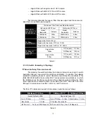
Gigabit Fiber with multi-mode LC SFP module
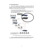
Fig. 2-2
Summary of Contents for GS-2224L
Page 1: ......
Page 2: ......
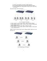
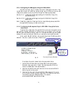
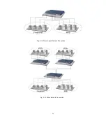
Page 34: ...24 Fig 2 15 Office Network Connection Fig 2 14 Peer to peer Network Connection ...
Page 78: ...68 Fig 3 28 ...
Page 83: ...73 Fig 3 31 ...
Page 91: ...81 Fig 3 39 Fig 3 40 Fig 3 41 ...
Page 113: ...103 Fig 3 67 Ingress Port Fig 3 68 ...
Page 115: ...105 Fig 3 71 Fig 3 72 Fig 3 73 ARP Fig 3 74 ARP ...
Page 116: ...106 Fig 3 75 ARP Fig 3 76 ARP Fig 3 77 ARP Fig 3 78 ARP ...
Page 117: ...107 Fig 3 79 ARP Fig 3 80 ARP Fig 3 81 ARP Fig 3 82 ARP ...
Page 118: ...108 Fig 3 83 ARP Fig 3 84 ARP Fig 3 85 ARP Fig 3 86 ARP Fig 3 87 ARP ...
Page 119: ...109 Fig 3 88 IPv4 Fig 3 89 IPv4 Fig 3 90 IPv4 ...
Page 120: ...110 Fig 3 91 IPv4 Fig 3 92 IPv4 Fig 3 93 IPv4 Fig 3 94 IPv4 Fig 3 95 IPv4 ...
Page 121: ...111 Fig 3 96 IPv4 Fig 3 97 IPv4 Fig 3 98 IPv4 Fig 3 99 IPv4 Fig 3 100 IPv4 ...
Page 122: ...112 Fig 3 101 IPv4 Fig 3 102 IPv4 Fig 3 103 IPv4 Fig 3 104 IPv4 ...
Page 123: ...113 Fig 3 105 IPv4 Fig 3 106 IPv4 Fig 3 107 IPv4 ...
Page 124: ...114 Fig 3 108 IPv4 Fig 3 109 IPv4 Fig 3 110 IPv4 Fig 3 111 IPv4 ...
Page 125: ...115 Fig 3 112 IPv4 Fig 3 113 IPv4 Fig 3 114 IPv4 ...
Page 126: ...116 Fig 3 115 IPv4 Fig 3 116 IPv4 Fig 3 117 IPv4 ...
Page 127: ...117 Fig 3 118 Action Fig 3 119 Rate Limiter ...
Page 128: ...118 Fig 3 120 Port Copy Fig 3 121 DMAC Filter ...
Page 129: ...119 Fig 3 122 VLAN ID Filter Fig 3 123 VLAN ID Filter Fig 3 124 Tag Priority ...
Page 141: ...131 Fig 3 126 Set up Policy Rules Fig 3 127 Set up Policy Rules Fig 3 128 Set up Policy Rules ...
Page 143: ...133 Fig 3 132 Set up Port Policies Fig 3 133 Set up Port Policies Finish ...
Page 159: ...149 Fig 3 145 ...
Page 204: ...194 Fig 4 1 Fig 4 2 ...

