36
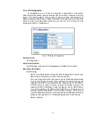
IP address:
Users can configure the IP settings and fill in new values if users set the
DHCP function “Disable”. Then, click
<Apply>
button to update.
When DHCP is disabled, Default: 192.168.1.1
If DHCP is enabled, this field is filled by DHCP server and will not allow
user manually set it any more.
Subnet mask:
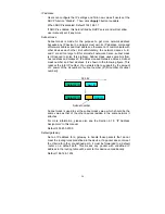
Subnet mask is made for the purpose to get more network address
because any IP device in a network must own its IP address, composed
of Network address and Host address, otherwise can’t communicate with
other devices each other. But unfortunately, the network classes A, B,
and C are all too large to fit for almost all networks, hence, subnet mask
is introduced to solve this problem. Subnet mask uses some bits from
host address and makes an IP address looked Network address, Subnet
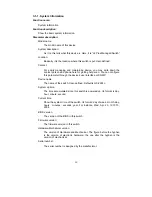
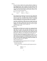
mask number and host address. It is shown in the following figure. This
reduces the total IP number of a network able to support, by the amount
of 2 power of the bit number of subnet number (2^(bit number of subnet
number)).
Subnet mask is used to set the subnet mask value, which should be the
same value as that of the other devices resided in the same network it
attaches.
For more information, please also see the Section 2-1-5 “IP Address
Assignment” in this manual.
Default: 255.255.255.0
Default gateway:
Set an IP address for a gateway to handle those packets that do not
meet the routing rules predefined in the device. If a packet does not meet
the criteria for other pre-defined path, it must be forwarded to a default
router on a default path. This means any packet with undefined IP
address in the routing table will be sent to this device unconditionally.
Default: 192.168.1.254
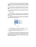
32 bits
Network ID
Host ID
Network ID
Host ID
Subnet number
Summary of Contents for GS-2224L
Page 1: ......
Page 2: ......
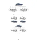
Page 34: ...24 Fig 2 15 Office Network Connection Fig 2 14 Peer to peer Network Connection ...
Page 78: ...68 Fig 3 28 ...
Page 83: ...73 Fig 3 31 ...
Page 91: ...81 Fig 3 39 Fig 3 40 Fig 3 41 ...
Page 113: ...103 Fig 3 67 Ingress Port Fig 3 68 ...
Page 115: ...105 Fig 3 71 Fig 3 72 Fig 3 73 ARP Fig 3 74 ARP ...
Page 116: ...106 Fig 3 75 ARP Fig 3 76 ARP Fig 3 77 ARP Fig 3 78 ARP ...
Page 117: ...107 Fig 3 79 ARP Fig 3 80 ARP Fig 3 81 ARP Fig 3 82 ARP ...
Page 118: ...108 Fig 3 83 ARP Fig 3 84 ARP Fig 3 85 ARP Fig 3 86 ARP Fig 3 87 ARP ...
Page 119: ...109 Fig 3 88 IPv4 Fig 3 89 IPv4 Fig 3 90 IPv4 ...
Page 120: ...110 Fig 3 91 IPv4 Fig 3 92 IPv4 Fig 3 93 IPv4 Fig 3 94 IPv4 Fig 3 95 IPv4 ...
Page 121: ...111 Fig 3 96 IPv4 Fig 3 97 IPv4 Fig 3 98 IPv4 Fig 3 99 IPv4 Fig 3 100 IPv4 ...
Page 122: ...112 Fig 3 101 IPv4 Fig 3 102 IPv4 Fig 3 103 IPv4 Fig 3 104 IPv4 ...
Page 123: ...113 Fig 3 105 IPv4 Fig 3 106 IPv4 Fig 3 107 IPv4 ...
Page 124: ...114 Fig 3 108 IPv4 Fig 3 109 IPv4 Fig 3 110 IPv4 Fig 3 111 IPv4 ...
Page 125: ...115 Fig 3 112 IPv4 Fig 3 113 IPv4 Fig 3 114 IPv4 ...
Page 126: ...116 Fig 3 115 IPv4 Fig 3 116 IPv4 Fig 3 117 IPv4 ...
Page 127: ...117 Fig 3 118 Action Fig 3 119 Rate Limiter ...
Page 128: ...118 Fig 3 120 Port Copy Fig 3 121 DMAC Filter ...
Page 129: ...119 Fig 3 122 VLAN ID Filter Fig 3 123 VLAN ID Filter Fig 3 124 Tag Priority ...
Page 141: ...131 Fig 3 126 Set up Policy Rules Fig 3 127 Set up Policy Rules Fig 3 128 Set up Policy Rules ...
Page 143: ...133 Fig 3 132 Set up Port Policies Fig 3 133 Set up Port Policies Finish ...
Page 159: ...149 Fig 3 145 ...
Page 204: ...194 Fig 4 1 Fig 4 2 ...

