Copyright © 2013 Ruckus Wireless, Inc.
Page 3 of 4
Published December 2013, Part Number 800-70453-001 Rev C
(O
PTIONAL
) M
OUNTING
I
NSTRUCTIONS
The R700 can be mounted to a T-bar, wall or ceiling a using
the enclosed mounting kit. Refer to the following sections:
•
Mounting to a Drop-Ceiling T-Bar
•
Mounting on a Flat Surface
Mounting to a Drop-Ceiling T-Bar
The enclosed T-bar bracket supports mounting to drop
ceiling T-bars.
1
Insert the unit removal pin (A in
Figure 1
) into the hole on
the side of the R700 (B in
Figure 1
) to release the locking
mechanism.
Figure 1. Attaching the T-bar bracket to the R700 AP
2
Position the studs on the bottom of the T-bar bracket (C
in
Figure 1
) in the mounting holes on the R700 enclosure,
and then slide the T-bar bracket away from the unit
removal pin until the studs are in the narrow parts of the
R700 mounting keyholes.
3
Remove the unit removal pin (A in
Figure 1
) to release
the locking mechanism and secure the T-bar bracket to
the R700.
4
Make sure that the locking tab (D in
Figure 1
) is in the
first position on the T-bar bracket (C in
Figure 1
).
5
Gently push the ceiling tiles up and out of the way.
6
Position the T-bar bracket so its two clasps grip one edge
of the T-bar (A in
Figure 2
). Make sure that both clasps
are gripping the T-bar.
Figure 2. Attaching the T-bar bracket to the T-bar
7
Hold the R700 in place and gently push the locking tab
(B in
Figure 2
) until its clasp grips the other edge of the T-
bar.
8
When you are done, the R700 is mounted.
9
To remove the AP:
•
Move the ceiling tiles out of the way.
•
Gently lift up the locking tab (A in
Figure 3
) by sliding
your fingers under the tab.
•
While lifting up on the locking tab, rotate the R700-
and-T-bar bracket assembly (B in
Figure 3
). The R700-
and-T-bar bracket assembly comes away from the T-
bar.
Figure 3. Removing the T-bar bracket from the T-bar
10
To remove the T-bar bracket from the AP:
•
Insert the unit removal pin (A in
Figure 4
) into the
hole on the side of the R700.
•
Gently lift up the retainer tab (B in
Figure 4
).
•
Gently push the T-bar bracket (C in
Figure 4
) toward
the unit removal pin until it detaches from the R700.
Figure 4. Removing the T-bar bracket from the AP
Mounting on a Flat Surface
1
Use the Mounting Template on the last page of this
Quick Setup Guide
as a template to mark the locations
for drill holes on the mounting surface. There are two
sets of keyholes available on the AP. One allows the AP
to be mounted to a wall or ceiling. The other allows the
R700 to be mounted to an accessory bracket (not
included).
2
Use a 5mm drill bit to drill holes approximately 25mm
into the mounting surface.
3
Insert the anchors and mounting screws into the mount-
ing surface, leaving approximately 1/4” (6 mm) of the
screw heads protruding for the AP enclosure.
4
Insert the unit removal pin into the hole on the side of
the AP to release the locking mechanism.
5
Place the AP onto the mounting screws so that the screw
heads enter the mounting holes on the AP enclosure,
and push the AP down to lock in place.
6
Remove the unit removal pin to release the locking
mechanism and secure the AP.
7
To remove the AP, insert the unit removal pin into the
hole on the side of the AP to unlock, then push the AP up
to release the AP enclosure from the mounting screws.
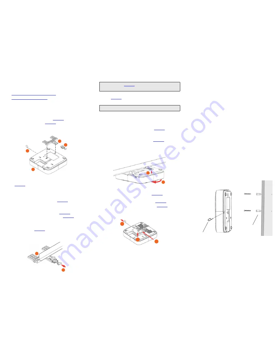
Figure 5. Flat surface mounting
A
B
C
D
A
B
Note:
For clarity,
Figure 2
only shows the T-bar bracket and
the T-bar, and does not show the R700 AP.
Note:
Make sure that all three clasps are gripping the T-bar!
A
B
C
B
A
Hold unit removal pin in
while mounting
Use template
to mark location
for drill holes


![Pentagram Cerberus [P 6367] Installation And Operation Manual preview](http://thumbs.mh-extra.com/thumbs/pentagram/cerberus-p-6367/cerberus-p-6367_installation-and-operation-manual_1524254-01.webp)
