5
ICE-Balancer
a
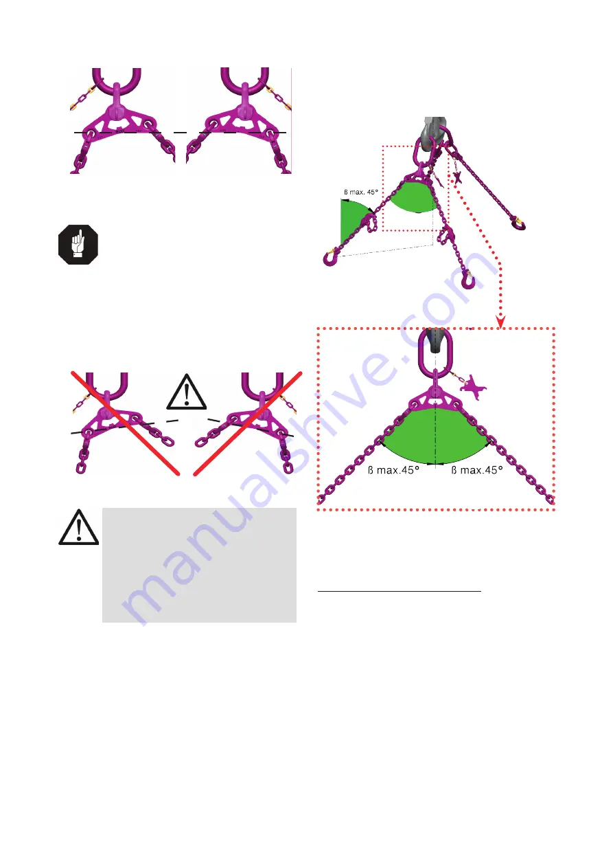
10°-edge
horizontal
10°-edge
horizontal
Pic. 11: Limit skewing inclination of 10° reached
(can be recognised by horizontal alignement of edge)
HINT
The maximum allowed balancer skewing
of 10° can be recognised by the specific
shape of the ICE-Balancer. The limit skew-
ing angle of 10° can be easily recognized.
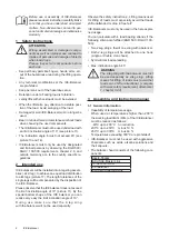
• A skewing of the balancer under load by more
than 10° is prohibited (Pic. 12)!
The 10° edge is no longer aligned horizontal!
The skewing of the balancer is too big.
Pic. 12: Skewing of the balancer by more than 10° is
prohibited.
WARNING
Skewing of the balancer by more than
10° is prohibited. Should the limit skewing
angle exceed 10°, an ICE-CURT-GAKO
length adjustment has to be installed into
the 2-leg balancer sling or a shortening
element must be used. Make chain strand
either longer or shorter until the balancer
is within the 10° range.
3.5 Hints for the usage
(Inclination angle
β
)
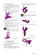
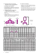
• Pay attention that the inclination angle ß will not
exceed 45° (see picture 13 and 14).
Pic. 13: Max. inclination angle
β = 45°
Pic. 14: Detailed view Pic. 13
4 Inspecting and repairing
4.1 Hints for the regularly inspection
The operator has to determine and dictate the nec-
essary inspection periods and the deadlines by a risk
assessment (see sections
4.2 and 4.3
).
The persisting appropriateness of the lifting mean
must be checked by a competent person (auditor) at
least once per year.
Depending on the conditions of use e.g. frequent use,
increased wear or corrosion, it may be necessary to
carry out inspections at shorter intervals than once per
year. A verification is also required following damage
and after special events.


