6
ICE-Balancer
Table 1:
Dimension chart of balancer
Subject to technical modifications
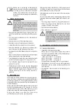
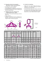
Pic. 15: Dimensioning of the ICE-Balancer
Chain
[mm]
Nomination
WLL of
balancer [t]
inclination
angle of legs
0-45°
WLL of
balancer [t] in-
clination angle
of legs 0° (±7°)
parallel
A
[mm]
B
[mm]
C
[mm]
D
[mm]
T
[mm]
weight
[kg/pc.]
Ref. no.
6
IW-6
2.5
3.6
110
15
14
21
46
0.49
7904367
8
IW-8
4.25
6.0
150
20
18
26
59
1.15
7904370
10
IW-10
7.1
10.0
180
25
23
32
76
2.4
7904372
13
IW-13
11.2
16.0
240
30
28
38
91
4.37
7904375
16
IW-16
17
25.0
300
35
32
41
120
8.8
7904255
L1
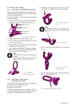
Pic. 16: Assembled chains
VV-SCH or
VC-SCH
IVS
Chain
[mm]
Nomination
ICE-Balancer
head
Dimensions
IAK- and
IA-Link [mm]
Top
connection
Bottom
connection
Pitch of
balancer
head
L1 [mm]
Weight of
balancer
head
[kg/pc.]
Ref. no.
balancer
head
6
IWK-2S-6
18x90x160
VV-SCH10 (4 t)
IVS-6
300
2.33
7904654
8
IWK-2S-8
26x100x180
VV-SCH13 (6.7 t)
IVS-8
363
5.39
7904655
10
IWK-2S-10
32x110x200
VV-SCH16 (10 t)
IVS-10
423
9.99
7904656
13
IWK-2S-13
36x140x260
VC-SCH 5.0 (25 t)
IVS-13
554
17.5
7904657
16
IWK-2S-16
46x190x350
VC-SCH 6.0 (31.5 t)
IVS-16
698
37.54
7904658
6
IWSAK-2S-6
26x190x350
VV-SCH 13 (6.7 t)
IVS-6
504
5.85
7907155
8
IWSAK-2S-8
32x190x350
VV-SCH 16 (10 t)
IVS-8
543
9.0
7907156
10
IWSAK-2S-10
36x250x460
VC-SCH 4.0 (16 t)
IVS-10
701
17.17
7907157
13
IWSAK-2S-13
40x250x460
VC-SCH 5.0 (25 t)
IVS-13
754
24.4
7907158
16
IWSAK-2S-16
47x250x460
VC-SCH 6.0 (31.5t )
IVS-16
808
37.2
7907159
Table 2:
Datas of ICE-Balancer head
Subject to technical modifications
4.2 Inspection criteria for the regularly
examination carried out by the operator:
• Completeness of the ICE-Balancer.
• Deformations at the component.
• Check readability of nominal size and manufacturer sign
• Mechanical damage like notches especially at
areas with tensile stress.
4.3 Additional inspection criteria for the
competent person resp. auditor
• Reduction of cross section cause by wear of more
than 10 %
• Strong corrosion
• Additional inspections may be necessary de-
pending on the result of the risk assessment (e.g.
incipient cracks at load bearing parts).
4.4 Hints for the Repairing
• Repair works can only be carried out by the ma-
nufacturer or by experts disposing necessary
knowledge and required skills.
• Only RUD original spare parts must be used and
all repairing and overhauling operations must be
documented in the chain card file (of the complete
lifting mean) or use the RUD BLUE-ID-System.


