3
LRBK-FIX
5
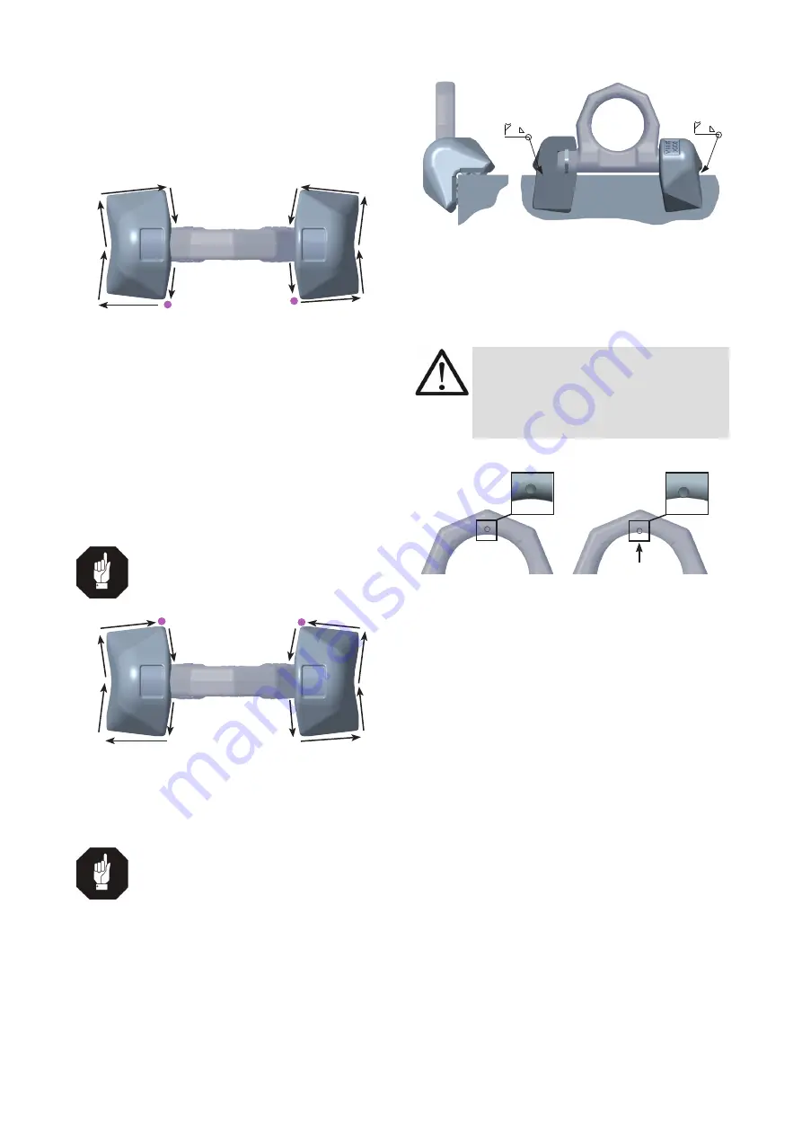
Begin at starting point S1 and weld subsequently the
sections 1-4 (
Pic. 1
).
6
Then weld the opposite side identically (starting point
S2 and chapter 5-8).
7
Afterwards close the rot pass at the inside areas (chapter
9-10 and 11-12).
S1
1
2
3
4
S2
11
12
9
8
7
6
5
10
Pic. 1: Welding sequence of the root run
(S=Starting point)
8
Finally please let the parts cool down.
9
Remove any welding mistakes and dirt at the root weld
before applying the cover weld seams.
10
Subsequently please weld the closure welds.
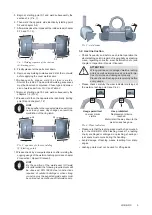
Start at the inside. The described welding sequences
must be observed compulsive. Chose type and dimen
-
sion of weld seam from
Pic. 3
and
Table 2
.
11
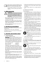
Begin at starting point S3 and weld subsequently the
chapters 1-6 (
Pic. 2
)
12
Please weld then the opposite side identically. (tarting
point S4 and chapter 7-12)
HINT
Please adhere the requested weld seam thick-
ness in any cases. Any change can result in a
malfulction of the ring latch.
S4
11
10
9
8
S3
7
12
1
2
3
4
5
6
Pic. 2: equence of closure welding
(S=Starting point)
13
Please check by a competent person after welding the
ongoing usage of the weld-on lashing point (see chapter
4 Inspection / Repair / Disposal
).
HINT
By the position of the weld-seam (HY-weld
circumferential) the following requirements will
be observed: DIN 18800 steel constructions
requires: at outdoor buildings or when strong
corrosion must be expected weld seams must
be carried out as continuous fillet weld seams.
+
+
Pic. 3: weld seam
3.4 User instruction
• Check frequently and before each initial operation the
whole lashing point in regard of linger ability as a lashing
mean, regarding corrosion, wear, deformation etc. (see
chapter
4 Inspection / Repair / Disposal
).
ATTENTION
Wrong positioned or damaged weld-on lashing
points as well as improper use can lead to inju-
ries of persons and damage at property.
Please check all lashing points carefully before
every usage.
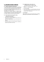
• Please check carefully the wear indicator markings of
the weld-on lashing point (see
Pic. 4
):
Usage permitted:
no wear marks
visible
Use prohibited:
Replacement criteria
reached.
Material all the way down to the
wear lenses has gone.
Pic. 4: Wear indicators
• Please note that the lashing mean must be free moveab
-
le in the LRBK-FIX. When lashing means (f.e. lashing
chain) are hinged or unhinged, no pinching, shearing or
joint spots must occure during the handling.
• Avoid damage of lashing means resulting from sharp
edges.
• Lashing points must not be used for lifting loads.


