8
5.
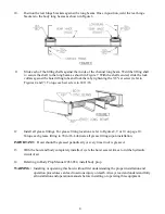
Slide a lock collar onto each lifting shaft. Slide a lifting shaft with collar into each end of the
hoist lifting tube (Figure 4).
6.
Position a mounting angle under each hoist saddle. Secure each mounting angle to the truck frame
by drilling two 17/32" dia. holes and bolting the large mounting angle to the truck frame. Finally,
weld each mounting angle to its respective hoist saddle. See Figure 5.
NOTE:
DO NOT
weld mounting angles or saddle flats to the truck frame.
NOTE:
All fasteners used in the above steps are 1/2" x 1 1/2" hex cap screws, lock washers, and
nuts. Torque all 1/2" fasteners to 90 ft. lb.
NOTE:
The hoist saddle must set directly on the truck frame. If rivet interference is encountered,
countersink the rivet heads into the hoist saddle.
7.
Install the hydraulic system using the Pump Installation & Operation Manual for the type of
pump being installed.
NOTE:
A listing of the Pump Installation & Operation Manuals is given on page #1 of this
manual.
8.
Position and secure the liner (sleeper) to the truck frame. The LR-416 or LR-165 hoist requires at
least 5 3/4" of clearance above the truck frame. As an example, if 4" long beams are on the truck
body, a liner of at least 1 3/4" will be required to gain enough room, 5 3/4", for mounting the LR-
416 or LR-165. Similarly, an LR-25 requires 7 1/2" of clearance.
9.
Position the body with the long beams (just long beams if they are separate from body) onto the
truck frame.
NOTE:
A clearance of at least 2" is required between the truck cab and the closest point on the
truck body.
Summary of Contents for 03 3018
Page 11: ...10 ...


