24.0
00497R0990 - 15-07-2000
D IE S E L
56
55
53
54
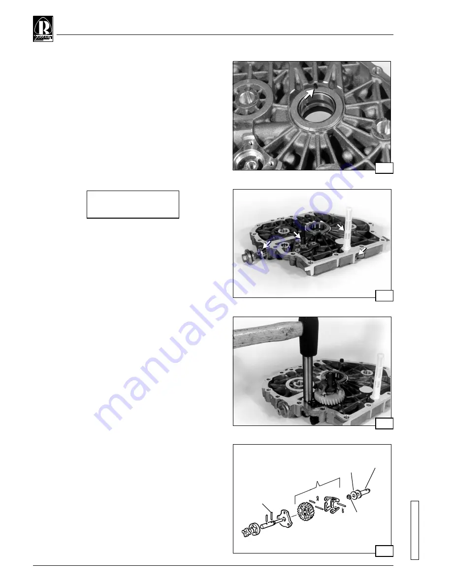
12.3 Timing system cover pre-assembly
Prepare the cover of the timing system in the following way:
1) Mount the main bearing as indicated in section 8.6 on page
12.
2) Fit in the pin and drive shaft bearing ring (fig 53).
3) Mount the oil pump rotors as described in section 9.11 on
page 17. Insert the plug and driving pin as shown in fig. 54-
A. Fix the oil pump cover in place by tightening the screws
to the following torque value:
4) Insert the by-pass valve using tool code 366.21 (fig. 55);
mount the by-pass check screw with Loctite 648; mount
the by-pass valve inspection plug on the outside of the
cover on the timing system side.
5) Fit the retainer cap on the oil intake duct at the base of the
cover on the timing system side, using Loctite 648 (fig. 54-
B).
6) Tighten the internal oil filter (fig. 54-C).
7) Fit on the engine oil filter and relative plug including the O-
Ring (fig 54-D).
8) Mount the rpm governor, in compliance with the alphabetical
sequence given in fig. 56.
9) Fit in the fuel flow limiter
10) Mount the oil retention ring as indicated on page 27 fig.67.
0.8
0.8
0.8
0.8
0.8 to
to
to
to
to 1.0 Kgm
1.0 Kgm
1.0 Kgm
1.0 Kgm
1.0 Kgm
(7.8
(7.8
(7.8
(7.8
(7.8 to
to
to
to
to
9.8 Nm)
9.8 Nm)
9.8 Nm)
9.8 Nm)
9.8 Nm)
A
A
A
A
A
B
B
B
B
B
E
E
E
E
E
C
C
C
C
C
D
D
D
D
D
A
A
A
A
A
A
A
A
A
A
B
B
B
B
B
B
B
B
B
B
C
C
C
C
C
C
C
C
C
C
D
D
D
D
D
D
D
D
D
D


