background image

27

COMPILER TECO/ATI

ENDORSED

DATE

29.02.2004

REG. CODE

1-5302-633

MODEL N°

 51074

DATE OF ISSUE

02-04

REVISION    

00

XI

36

37

38

39


D

1

2

9

7

5

3

4

6

8

10


G


F


E


B


C


A


H


L


I


M


O


P


N

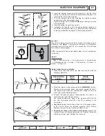
0,24

5

0,25

INJECTION EQUIPMENT

Number
of holes

Diameter of steel

wire (mm)

Diameter

of holes (mm)

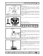
2. Mount the injector on the test bench (code 

00365R0430

, fig. 40).

Disconnect the pressure gauge and rapidly operate the lever.
The nozzle must make the characteristic "trilling" sound and
inject with a good atomizing action.

3. Connect the pressure gauge. Slowly depress the level in a

continuous way until injection occurs.
The injector needle must "open" at the pressure of 230 to 238
bar. Vary the washer shims (N° 5 fig. 38) to calibrate in the
correct way.

4.

Leak test:

 operate the test bench lever until the gauge pointer

is 20 Kg/cm² below the injection pressure value. Nozzle
tightness is good if no fuel comes out within 10 sec.

5.

Checking for leaks on the nozzle return phase:

 operate the

test bench lever until the gauge pointer is 20 Kg/cm²  below the
injection pressure value. Release the lever and

Leak test

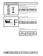
Plug the fuel return union and let air in through the fuelling union at
a pressure of 

6 Kg/cm²

. Fully immerse the pump in a receptacle

containing diesel fuel for about 50 - 60 seconds (fig. 37) and make
sure that no bubbles appear.

NOTE: the position of the pump adjuster sleeve is of no importance
for this test.

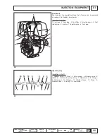
Injector

Details of fig. 38:

1. Filter - 2. Fuel inlet union - 3. Fuel return union - 4. Nozzle holder
- 5. Calibration washer - 6. Spring - 7. Pressure rod - 8. Spacer - 9.
Nozzle - 10. Ring nut.

Injector inspection and calibration

1. Clean the nozzle holes with a thin steel wire (fig. 39) with the

following diameters:

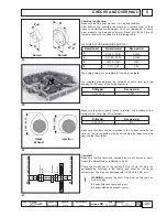
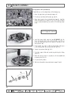
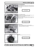
5. Insert the adjuster sleeve unit and plunger (L) into the pump

casing (A), making sure that the helical profile is directed on a
level with the return union with ball.

6. Fit in the adjuster block (M), matching the reference marks

applied during the demounting phase.

7. Tighten the plug (N) to a 

0.5 to 0.6 Nm

 torque, locking it in place

with Loctite 290.

8. Insert the spring (O) and lower cap (P).
9. Compress the tappets in the various operating positions to

check that the adjuster sleeve (L) slides perfectly. Resistance
or jamming will make the engine to hunt during operation.

Summary of Contents for RY125 Series

Page 1: ...1 COMPILERTECO ATI ENDORSED DATE 29 02 2004 REG CODE 1 5302 633 MODEL N 51074 DATE OF ISSUE 02 04 REVISION 00 RY125 1st Edition WORK SHOP MANUAL RY 125 series engines p no 1 5302 633...

Page 2: ...ines have been adequately trained and outfitted to safely and professionally carry out the necessary tasks 2 The persons who service Ruggerini engines possess the necessary skills and special Ruggerin...

Page 3: ...ire special written warranty agreements Within the above stated periods Lombardini Srl directly or through the Ruggerini Motori authorized network will repair and or replace free of charge any own par...

Page 4: ...INTENANCE RECOMMENDED OIL TYPE REFILLING_______________________________ 15 IX DISASSEMBLY OF THE ENGINE _________________________________________________ Page 17 Demounting and remounting the main bea...

Page 5: ...______________________ Page 29 Characteristics of the system 29 Checking the alternator 30 Checking the system 29 Ring gear 30 XIII ENGINEASSEMBLY _____________________________________________________...

Page 6: ...39 XV STORAGE ___________________________________________________________________ Page 40 Setting at work 40 Storage for up to 6 months 40 Storage periods of more than 6 months 40 XVI QUICKREFERENCECH...

Page 7: ...idle operation Incomplete running in Engine overloaded Advanced injection Delayed injection Incorrect governor linkage adjustment Broken or loose governor spring Idle speed too low Worn or jammed pis...

Page 8: ...ous danger for his personal safety and health and that of any persons who may be in the vicinity of the machine Theenginemayonlybeusedorassembledonamachinebytechnicianswhoareadequatelytrainedaboutitso...

Page 9: ...ever carry out any operation whilst the engine is running The coolant fluid circuit is under pressure Never carry out any inspections until the engine has cooled and even in this case only open the ra...

Page 10: ...02 2004 REG CODE 1 5302 633 MODEL N 51074 DATE OF ISSUE 02 04 REVISION 00 III MODEL NUMBER AND IDENTIFICATION ENGINE IDENTIFICATION Engine Serial Number Approval code Customer s code R P M setting R P...

Page 11: ...e Nm rpm 31 2000 Fuel consumption max torque g kWh 250 Oil consumption kg h 0 0055 Capacity of standard oil sump lt 1 5 Recommended battery 12V in standard start conditions Ah A 50Ah 255A DIN Recommen...

Page 12: ...le load NA ISO 3046 1 ICXN CONTINUOS RATING WITH OVERLOAD CAPABILITY continuos heavy duty with constant speed and constant load MN Torque at N power MB Torque at NB power MA Torque at NA power C Speci...

Page 13: ...SSUE 02 04 REVISION 00 VI PRESADIFORZASUALBEROACAMMEOPZIONALECONSENSO DIROTAZIONEDESTRO OPTIONALP T O ONCAMSHAFTWITHCLOCKWISEDIRECTIONOF ROTATION PRESADIFORZASTANDARDCONSENSODIROTAZIONE SINISTRO STAND...

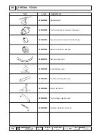
Page 14: ...365R0100 00366R0210 00365R0430 00366R0240 00365R0940 SPECIAL TOOLS TOOL CODE DESCRIPTION Flywheelpuller Tool to mount and demount main bearings Plug to mount and demount main bearings Sleeve to insert...

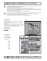
Page 15: ...as used in cars Use of other types of fuel could damage the engine The cetane rating of the fuel must be higher than 45 to prevent difficult starting Do not use dirty diesel fuel or mixtures of diesel...

Page 16: ...The risk of piston seizure jammed piston rings and rapid wear of the cylinder liner the bearings and all moving parts increases if oil whose characteristics differ from the recommended type is used or...

Page 17: ...ndicated in fig 1 Removing the injection pump Mark the position of the injection pump in relation to the engine casing if this has not already been done Remove the injection tube and take out the fuel...

Page 18: ...tool code 00365R0900 with plug code 00366R0220 and sleeve code 00366R0230 side A fig 7 To mount the main bearing on the cover on the timing system side use tool code 00365R0900 with plug code 00366R02...

Page 19: ...metal brush and replace them if the tops are deformed cracked or worn fig 9 with guide mounted measurements in mm Check the dimensions of the valve stem fig 10 and the play between the guide and valve...

Page 20: ...rings Check the length of the spring as indicated in fig 13 to identify any yielding Replace the springs if the values are different Rocker arms Make sure that there are no evident signs of wear on th...

Page 21: ...fig 17 Replace the piston and rings if the play exceeds WARNING it is advisable to replace the piston rings whenever the piston is demounted Checking the piston diameter the diameter of the piston mus...

Page 22: ...erpendicular positions fig 22 Grind the shaft if the wear exceeds the values in the table by 0 08 mm or more Undersized bearings can be mounted without any reaming work required WARNING do not remove...

Page 23: ...S AND PLAY The entire pump must be replaced if the wear is greater The coupling play between the external oil pump rotor and the housing on the cover of the timing system is Make sure that the oil pum...

Page 24: ...the tappets fig 28 Replace the parts if necessary Tapet and housing coupling play The rods must be straight with ball shaped surfaces at the ends and in good conditions fig 28 Injection pump tappets...

Page 25: ...on 2 Filler 3 Valve spring 4 Delivery valve 5 Washers 6 Monobloc pump casing 7 Adjuster seal 8 Flange 9 Pump seal 10 Plunger 11 Adjuster sleeve 12 Plug 13 Adjuster block 14 Spring 15 Lower cap Fuel ci...

Page 26: ...op is more that 50 Kg cm and continues to slowly drop lower The pressure must drop from 200 Kg cm to 150 Kg cm in not less than 7 sec Injection pump calibration fig 34 When the adjuster sleeve is 10 5...

Page 27: ...injection pressure value Release the lever and Leak test Plug the fuel return union and let air in through the fuelling union at a pressure of 6 Kg cm Fully immerse the pump in a receptacle containing...

Page 28: ...ves the pressure exercised by the spring on the ring nut 1 Visual inspection make sure that the needle housing is not deformed or excessively rough The nozzle body must not show signs of wear or damag...

Page 29: ...tor 8 Low oil pressure indicator CABLES Colour x Section mm2 CABLE COLOURS B white M brown N black R red V green Checking the system 1 make sure that the connections between the regulator and alternat...

Page 30: ...fig 47 Accelerate the engine to 3000 rpm The voltage must be 33V If the values are more than 10V less than this it means that the rotor is demagnetized and that the alternator must be replaced Warning...

Page 31: ...using in the engine casing Fit the screw into the guide as shown in fig 51 Preparing the engine block Remove all traces of sealant or impurities from the bearing surfaces with a copper plate or lappin...

Page 32: ...pump cover in place by tightening the screws to the following torque value 4 Insert the by pass valve using tool code 00366R0210 fig 54 mount the by pass check screw with Loctite 648 mount the by pas...

Page 33: ...aft Insert the counter shaft matching the reference marks on the gears fig 59 Connecting rod drive shaft connection After having fitted the bearings into the small end connect the connecting rod to th...

Page 34: ...ce a calibrated bar on the cover of the timing system on a level with the engine casing retention surface and use a thickness gauge to check the distance between the bearing ring and bar fig 62 Note d...

Page 35: ...s making sure that the five shorter ones 40 mm are mounted in the top part of the cover Tighten to the following torque value Oil retention rings 1 Immerse the retention ring in oil for about 10 minut...

Page 36: ...ve the piston to TDC top dead center and check that the mark stamped on the flywheel corresponds to the reference pointer of the tool code 00366R0240 fig 75 To obtain the correct clearance use a head...

Page 37: ...curately adjusted it is advisable to define the shims to insert under the pump by measuring the dimension between the pump bearing surface and the tappet Proceed in the following way 1 turn the flywhe...

Page 38: ...block fig 77 Fit the injection pump into the engine block and keeping it pressed down fix it in place by tightening the nut that holds the relative bracket Match the marks made during the demounting p...

Page 39: ...the following operations after having positioned the engine on the brake 1 Start the engine and allow it to idle 2 Allow the engine to run in before checking the maximum power There may be hunting pr...

Page 40: ...type SAE 10W into exhaust and intake manifolds rocker arms valves tappet etc Grease all unpainted parts Loosen belt Wrap the engine in a plastic film Store in a dry place if possible not directly on t...

Page 41: ...0 8 2 2 0 1 MAX mm 0 25 0 25 0 3 0 5 0 15 0 20 1 2 7 0 4 QUICK REFERENCE CHARTS Spiel mm Grezen mm Couplings Camshaft and plugs Compression ring opening Oil scraper ring opening Connecting rod and pi...

Page 42: ...N mm2 R 1200 N mm2 Nm 3 6 7 12 19 8 29 6 38 52 5 89 135 205 257 358 435 557 kgm 0 37 0 72 1 23 2 02 3 02 3 88 5 36 9 09 13 80 21 00 26 30 36 60 44 40 56 90 4 x 0 70 5 x 0 80 6 x 1 00 7 x 1 00 8 x 1 2...

Page 43: ...ockwise direction and check the comparator to make sure that the piston rises by the values indicated in the following table in relation to TDC dimension h fig 2 8 Remove the injection tube and mount...

Page 44: ...r n importe quel moment les donn es report es dans cette publication Data reported in this issue can be modified at any time by Lombardini Lombardini vorbeh lt alle Rechte diese Angabe jederzeit ver n...

Reviews: