background image

3

1. Safety Instructions

!!! The safety instructions have to be observed during the installation, operation, cleaning and
     servicing of the Rühle High Tech Cutter type SR 1 and SR1 turbo.

1.1 Safety hints

!!! The operating manual has to be read by the supervising personal before installation, operation,
     cleaning or servicing. The supervising personal has to make sure, that the operator as well as
     the persons cleaning and servicing the machine, have read and understood the operating
     manual.

!!! The operator has to operate the machine as directed and strictly pay attention to all points of the
     operating manual. The supervisor has to write an instruction for the intended use of the
     machine.

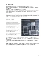
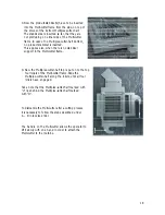
!!!  Before starting up the machine, the operator has to check the functionality of the following
     safety devices on a day to day basis:

A.


Visual control on all sides of the machine for changes or damage. In


     case of  changes or damage, the machine has to be shut down.


B.


Close the door to the cutting area – lock discharge funnel inside the cutting area
door – start the machine – open the cutting area door 20 mm. Should the machine
not stop it has to be shut down immediately.
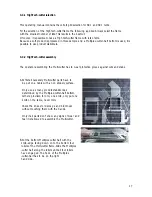
 

C.


Close the door to the cutting area – close process shaft – start the machine – open

                      the process shaft. If the machine doesn’t stop, it has to be shut down immediately.


D.


Lock the brakes of the casters at the back. – Try to move the machine by pushing

                      it. – Select a different location if the machine moves and shut the machine down
                      immediatly should the new location result in movement again

To shut down the machine, the main switch has to be turned to position”0”. Additionaly, the
main switch has to be secured by a pad lock. The key has to be handed over to the
supervisor. The mains plug has to be disconnected from the power outlet.

   !!! The supervising personal has to make sure, that the malfunctioning safety devices
       are repaired by a Rühle technician. It’s the supervisors responsibility, that the machine isn’t
       used under any circumstances until the repairs have been carried out.

   !!! The cleaning personal has to observe the cleaning instructions.
       The supervisor has to write instructions for a safe cleaning procedure.

   !!! The maintenance personal is only allowed to service the machine within the guidelines of
       ”regular maintenance 5.1” unless written permission has been given by the manufacturer
       to do otherwise. The supervisor has to write instructions for safe maintenance works.

Summary of Contents for SR1 turbo

Page 1: ...semi automatic High Tech Cutter SR1 and SR1 turbo R hle GmbH Lebensmitteltechnik Beim Signauer Schachen 10 79865 Grafenhausen Tel 49 7748 523 0 Fax 49 7748 52385 00 10 2001 CR www Ruhle biz M a n u a...

Page 2: ...4 2 HighTech cutter assembly 17 3 4 3 HighTech cutter installation 19 3 4 4 HighTech cutter maintenance 20 3 5 The sectioning Blade 20 3 6 The Tool box 21 3 7 Feeding the machine 22 3 7 1The work ben...

Page 3: ...op it has to be shut down immediately C Close the door to the cutting area close process shaft start the machine open the process shaft If the machine doesn t stop it has to be shut down immediately D...

Page 4: ...of the European Standard pr EN XXX Cutting machines for cubes edition 3 1998 This machine is not fitted with an emergency STOP device because there is no risk for the operator and the product The OFF...

Page 5: ...5...

Page 6: ...mages caused by violation of these instructions The transport of the machine has to be carried out according to the operating manual Main switch Cutting length adjustment lever Pre compacting adjustme...

Page 7: ...that a passable safety path of one meter in width is all around the machine No objects which could change the centre of gravity or the total weight should be lying on the machine during transport The...

Page 8: ...e machine This is followed by cleaning and disinfecting of the machine according to the cleaning instructions All accessories have to be checked for visible damage a possible cause of the transport du...

Page 9: ...n The machine has to be adjusted to the product prior to the cutting process The adjustment consist of inserting the correct multi grid combination choosing The right cutting length forward feed lengt...

Page 10: ...nged after a written confirmation by the R hle GmbH The best product adjustment is achieved with the help of a R hle service technician There is a choice of different adjustment variables for each pro...

Page 11: ...ool 4 C 6 6 6 0 4 4 Pork cool 4 C 10 10 10 0 4 Adjustment Meat cut into stripes Nr Material State Multi cutter Bottom mm Multi cutter Top mm Length mm Pre Comp 1 Pork cold 0 C 60 12 6 4 2 Pork cool 4...

Page 12: ...tment Meat salad with mayonnaise Nr Material State Multi cutter Bottom mm Multi cutter Top mm Lengthmm Pre Comp 1 Pork cool 4 C 0 6 2 0 2 2 Pork cool 4 C 30 6 3 0 2 3 Pork cool 4 C 6 6 6 0 2 4 Pork co...

Page 13: ...h mm Pre Comp 1 Beef cool 4 C 30 30 10 0 6 2 Beef cool 4 C 60 60 3 0 2 3 Pork cool 4 C 60 6 3 0 6 Adjustment Pork head Nr Material State Multi cutter Bottom mm Multi cutter Top mm Length mm Pre Comp 1...

Page 14: ...Nr Material State Multi cutter Bottom mm Multi cutter Top mm Length mm Pre Comp 1 Pork cool 4 C 10 0 10 0 6 2 Beef froz 3 C 6 0 3 0 6 Adjustment Steak With sectioning blade and Multi cutter frame Nr M...

Page 15: ...ard soft 12 12 12 6 3 soft hard 12 60 6 0 6 4 soft hard 10 10 6 0 6 5 hard soft 6 60 3 0 4 Adjustment Potatoes Nr Material State Multi cutter Bottom mm Multi cutter Top mm Length mm Pre Comp 1 Carrots...

Page 16: ...tter parts are mounted and the frame itself is attached to the machine The Multiplex cutter half Top is marked with O Over and as the second cutting stage moves one plane of knives The Multiplex cutte...

Page 17: ...protective gloves against cuts and stabs A At first all necessary Multi cutter parts have to be put on a table with a non slippery surface Only use as many product stabilizers as determined by the Mul...

Page 18: ...upport in the Multi cutter frame D Now the Multiplex cutter half top is put on to the top four rollers of the Multi cutter frame Slide the Multiplex cutter half along the rollers until all four roller...

Page 19: ...efore sliding the Multi cutter into the Multi cutter fastener it has to be inserted into the sector of the sheet metal as high up as possible Now the Multi cutter can be inserted into the fastener D T...

Page 20: ...n an even blunter knife Again use special protective gloves against cuts and stabs The R hle knife sharpener is well balanced and has as one of its components Vidia steel The construction of the sharp...

Page 21: ...r halves 5 stabilizers and 1 knife sharpener this means good order safety and hygiene for all the accessories and the operator Should the machine be equipped with special plunger plates then these Ite...

Page 22: ...fter cleaning All sorts of preparations can be carried out on the work bench from arranging to cutting 3 7 2 The shaft charging The filling of the shaft is decisive for the cut appearance that s why s...

Page 23: ...when the bottom part of the slider lies against the machine and when the machine starts working automatically with a started process program 3 8 Product discharge The product discharge for SR 1 and SR...

Page 24: ...he supervisor about defects of the machine immediately The cleaning personal has to use the recommended cleaning agents and disinfectants Don t make any alterations to the machine The cleaning agents...

Page 25: ...nking water from a water hose or a pressure cleaner to hose down the machine and the dismantled attachments which have to be in a secured position in the temperature range from 50 60 C according to th...

Page 26: ...gular maintenance has to be carried out at least once a week This allows little errors or wear and tear to be detected before a major damage occurs Not performing regular maintenance leads to technica...

Page 27: ...rvice on the machine has to be performed every 2000 operating hours or at least once a year in case that the machine has not been running for 2000 hours The regular service consists of the following s...

Page 28: ...e inserted wrongly Grid halves put together incorrectly Feeding system doesn t operate Operating terminal is not switched on Emergency Stop because not all safety switches are connected Machine doesn...

Page 29: ...ne These diagrams are kept inside the switch box in order to have them handy for the service technician In case of reselling the machine the circuit diagrams have to be handed over as well 6 2 List of...

Page 30: ...ervice interval p 32 Compressed air p 34 Machine feet p 7 Service p 1 34 35 Conformity decl p 5 Multicutter p 18 Sharpening p 22 Data plate p 34 Multiplex cutter half p 18 Spare parts p 35 Disinfectin...

Reviews: