LaserCuttistV1.2 Laser Cutting system
RuiDa Technology E-Mail:
support@rd-acs.com
1TH FLOOR,5TH BUILDING,NANYOU
TIANAN INDUSTRIAL ZONE,SHENZHEN
Web:
www.rd-acs.com
Phone: (086)0755-26066687
FAX: 0755-2698287
13
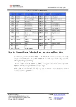
Figure 2-3 CN2~CN5 signal definition
pin
signal
description
pin
signal
description
PIN1
OGND
24Vreferenced ground
PIN14
OVCC
24Voutput
PIN2
ALM
Servo alarm input
PIN15
CLR
Servo reset output
PIN3
SON
Servo on
PIN16
NC
NC
PIN4
A0-
ENCODER A-
PIN17
A0+
ENCODER A+
PIN5
B0-
ENCODER B-
PIN18
B0+
ENCODER B+
PIN6
C0-
ENCODER C -
PIN19
C0+
ENCODER C+
PIN7
+5V
+5V output
PIN20
GND
Digital ground
PIN8
Vout
Speed referenced
command
PIN21
GND
Digital ground
PIN9
DIR+
DIR+
PIN22
DIR-
Dir-
PIN10
AGND
Analog referenced
ground
PIN23
PULSE+
Pulse+
PIN11
PULSE-
Pulse-
PIN24
GND
Digital ground
PIN12
NC
NC
PIN25
NC
NC
PIN13
GND
Digital ground
Step 6
:
Connect Laser following head, air valve and laser tube
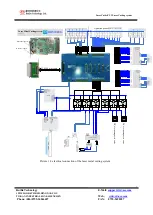
Laser following head is controlled with IOs on the RDS3040G terminal board. There are usually
relays between the IO and the devices. The RDS3040G control the relays and the relays control the
following head rising and following.
On the terminal board, the IO(CN10—OUT25) is assigned to the “rise” control output. The
IO(CN10—OUT24) is assigned to “follow” control output.
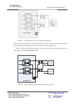
Out24, out25 has almost 300mA current ability and can drive the relays directly.The electrical
connection is shown as picture 2-6.

