LaserCuttistV1.2 Laser Cutting system
RuiDa Technology E-Mail:
support@rd-acs.com
1TH FLOOR,5TH BUILDING,NANYOU
TIANAN INDUSTRIAL ZONE,SHENZHEN
Web:
www.rd-acs.com
Phone: (086)0755-26066687
FAX: 0755-2698287
15
Step 7
:
connect the dedicated IO for X
、
Y axis motors
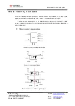
The signal for the motor control include
:
LIMIT input
、
HOME input
。
If there servo motors, There are still include
SERVO ON and ALARM input.
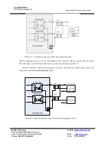
The HOME and LIMIT ,SERVO ON ,ALARM signals are all
Photoelectric isolated. Just is shown as
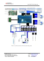
picture 2-8.
Picture2-8 Dedicated input and dedicated output signal
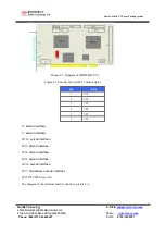
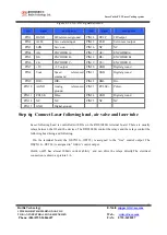
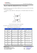
The definition of the dedicated IO is described in Figure 2-8 in detail.
Figure 2-8 Definition of the dedicated IO in CN11
pin
signal
description
pin
signal
description
PIN1
HOME0
HOME input for axis
X
PIN9
LMT2+
LIMIT+ input for axis
Z+
PIN2
HOME1
HOME input for axis
Y
PIN10
LMT2-
LIMIT- input for axis Z-
PIN3
HOME2
HOME input for axis
Z
PIN11
LMT3+
LIMIT+ input for axis
A+
PIN4
HOME3
HOME input for axis
A
PIN12
LMT3-
LIMIT- input for axis A-
PIN5
LMT0+
LIMIT+ input for axis
X+
PIN13
OVCC
24V power output
PIN6
LMT0-
LIMIT- input for axis
X-
PIN14
OVCC
24V power output
PIN7
LMT1+
LIMIT+ input for axis
Y+
PIN15
OGND
24V referenced ground
PIN8
LMT1-
LIMIT- input for axis PIN16
OGND
24V referenced ground

