background image

RG-S7800C  Switch  Quick  Installation  Guide,  V1.2 


Installing  the  Switch


15 


The  total  power  of  power  supplies  of  the  RG-S7800C  must  be  greater  than  the  working  power  of  the  host.  Otherwise,  some 

modules may fail to start. 


The host power is the summation of the power of all working modules, including the supervisor module, service module and fan. 

For the power of each module, see 

RG-S7800C Series Switches Installation and Reference Guide.


4.9  Installing Fans 

The fan tray model of the RG-S7808C and RG-7805C is M08-FAN and M05C-FAN respectively. Before the following procedures, 

wear an anti-static wrist trap close to your skin and have it properly grounded. 


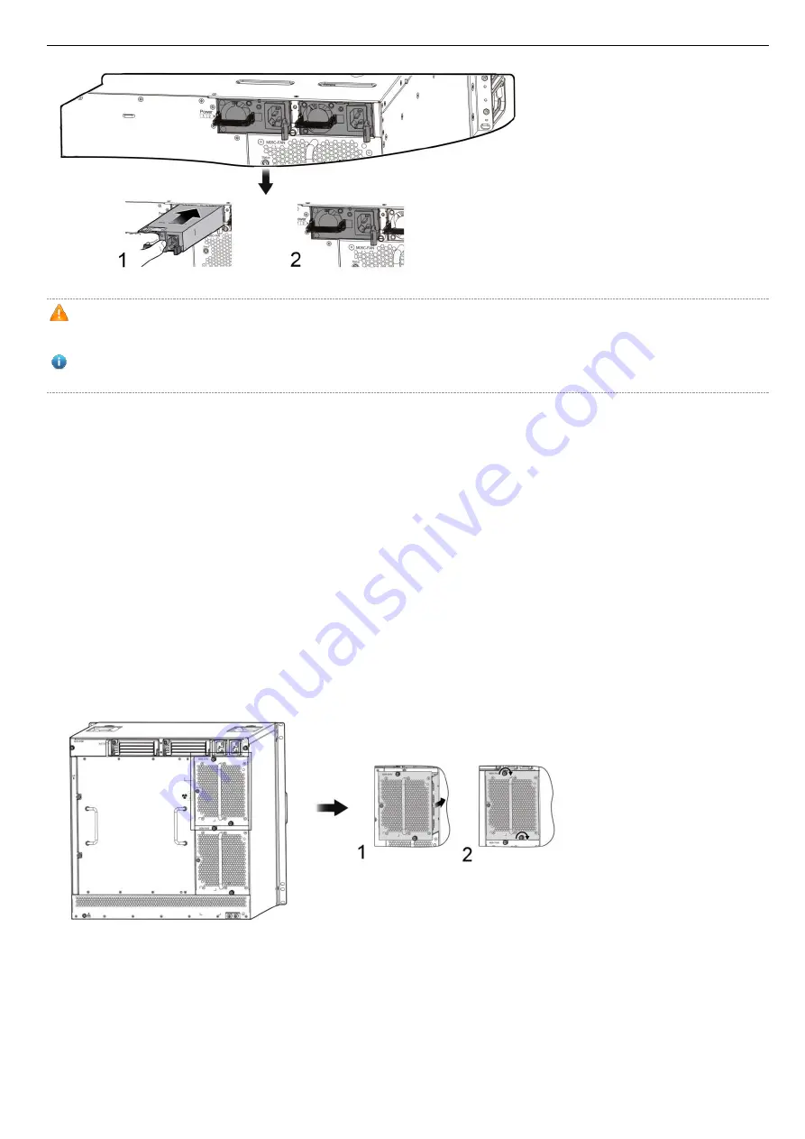
Steps for installing the M08-FAN fan tray: 

1)  Install the fan tray into the fan slot in the back panel of RG-S7808C. Make sure that the fan is installed properly. 

2)  Tighten the captive screws on the fan tray with a screwdriver. 


Figure 4-14 Installing M08-FAN   


Steps for installing the M05C-FAN fan tray: 

1)  Install the fan tray into the fan slot in the back panel of RG-S7805C. Make sure that the fan is installed properly. 

2)  Tighten the captive screws on the fan tray with a screwdriver. 

Summary of Contents for RG-S7800C Series

Page 1: ...Ruijie RG S7800C Series Switches Quick Installation Guide V1 2...

Page 2: ...or by any means without the prior written consent of Ruijie Networks is prohibited Exemption statement This document is provided as is The contents of this document are subject to change without any n...

Page 3: ...ted Documents Documents Description Configuration Guide Describes network protocols and related mechanisms that supported by the product with configuration examples Command Reference Describes the rel...

Page 4: ...LMESH architecture RG S7800C series switches support dual supervisor modules and power supply redundancy There are two models available Designed with eight horizontal slots RG S7808C series support du...

Page 5: ...re may be more than one power cord Remove the power supply fans and service modules to reduce the chassis weight before moving the switch for a long distance At least two people are needed to move the...

Page 6: ...nti static wrist strap The anti static wrist strap is shipped with RG S7800C which is used as follows 1 Stretch out your hand into the anti static wrist strap 2 Lock the wrist strap and make sure that...

Page 7: ...hapter of RG S7800C Series Switches Hardware Installation and Reference Guide for details 3 3 Cabinet Mounting Make sure the cabinet complies with the following conditions Install the switch in a 19 i...

Page 8: ...on Tools Cross screwdriver straight screwdriver related electric and optical cables Bolts diagonal pliers straps Special Tools Anti static glove stripping pliers crimping pliers crimping pliers for th...

Page 9: ...p yellow green grounding wires quick installation guide packing list Module Carton Modules packing list documentation A normal delivery should contain the above mentioned items which may differ from t...

Page 10: ...Switch 4 1 Installation Flowchart Figure 4 1 Installation Flowchart 4 2 Installing Slide Rails When installing slide rails for the RG S7800C ensure that the plane to carry the chassis should be instal...

Page 11: ...e RG S7800C switch is installed If you are mounting multiple devices to the cabinet mount the heaviest device in the lowest position of the cabinet first and proceed to mount the rest of the devices f...

Page 12: ...Frame Optional The PoE power frame M78 PSE is an optional accessory for the RG S7808C See RG S7800C Series Switch Installation and Reference Guide for details The PoE power frame is not supported on t...

Page 13: ...kets are mounted properly as shown in figure 4 6 3 Align the screw holes on the cable management brackets with those on the chassis and tighten the screws as shown in figure 4 6 Figure 4 6 Mounting Ca...

Page 14: ...acle in the frame and the surrounding environment Prepare the equipment and move it to the place near the cabinet where you can handle it easily It is recommended to have three people carry or lift th...

Page 15: ...ble maximum current Cables of good conductor should be used Do not use bare wire To ensure security the switch should be well grounded The grounding resistance for combined grounding should be less th...

Page 16: ...g The socket outlet shall be installed near the equipment and shall be easily When installing the unit always make the ground connection first and disconnect it last The cross sectional area of protec...

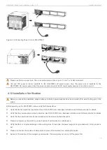
Page 17: ...operation is greater than 30s Please do not touch the golden finger part of the power supply which is removed after power off in case that capacitor discharge is not full Install the AC power system o...

Page 18: ...model of the RG S7808C and RG 7805C is M08 FAN and M05C FAN respectively Before the following procedures wear an anti static wrist trap close to your skin and have it properly grounded Steps for insta...

Page 19: ...an anti static wrist strap when installing the module and the metallic part of the anti static wrist strap should be fully touched with the skin Besides for the sake of security please not touch any...

Page 20: ...service module adopt the design of self locking lever See figure 4 13 for operation 1 Lever Operation Figure 4 18 Pulling out Lever 2 Module Installation on RG S7808C 1 Pull out both levers in figure...

Page 21: ...the panel in figure 4 20 Figure 4 20 RG S7805C in Chassis 4 11 Connecting the Power Cord Connect the power cord to the location as required according to the identification on the power module panel in...

Page 22: ...ore powering up the RG S7800C please verify the following items Verify that the fan meets the requirement See RG S7800C Series Hardware Installation and Reference Guide for details Verify that the pow...

Page 23: ...is connected properly and won t be loosened Verify that the power cord is long enough to avoid being stretched Verify that the rated current of the external power socket is greater 16A and that the so...

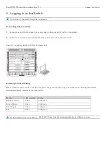
Page 24: ...t on the supervisor module Figure 5 1 Connecting Switch to PC through Console Port Powering on and Checking Make sure that the power cord is connected to the power supply and the power supply is opera...

Reviews: