background image


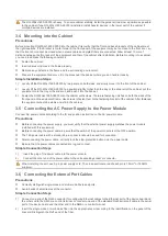
All expansion bolts for fastening the cabinet base to the ground should be installed and tightened in sequence from 
bottom up (large plain washer, spring washer, and nut), and the installation holes on the base and the expansion 
bolts should be well aligned. 


After the cabinet is installed, it should be stable and still. 


After the cabinet is installed, it should be vertical to the ground. 


When multiple cabinets are put side by side in the room, they should be aligned in a straight line, with an error less 
than 5 mm. 


The front/back doors of the cabinet should be properly installed. You can open and close them smoothly. The locks 
should work normally, and all keys should be complete. 


There should be no unnecessary formal labels inside the cabinet and on various boards. 


Blank panels should be installed completely. 


Fastening screws of various devices in the cabinet of the same model should be ready and tightened. 


Various boards of the equipment should be installed securely, and the fastening screws on the panel should be 
tightened. 


All wiring inlets at the top and bottom of the cabinet should be installed with rodent-resistant nets where the seams 
should be no more than 1.5 cm in diameter, to prevent rodents and other small animals from entering the cabinet. 


Antistatic wrist straps should be provided in the cabinet. 

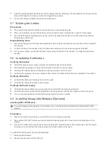
Installation Steps 

1) 

Plan the available space before installing the cabinet. You must reserve sufficient space for front and back doors for 
maintenance. 

2) 

Mount and fasten the cabinet at the designed location as planned. 

3) 

Install the appropriate cable management bracket and cables. 

4) 

Install the tray and wiring layer on the rack according to the configuration of one rack with one cabinet installed or 
one rack with multiple cabinets installed. 

Guide Rails Installation 

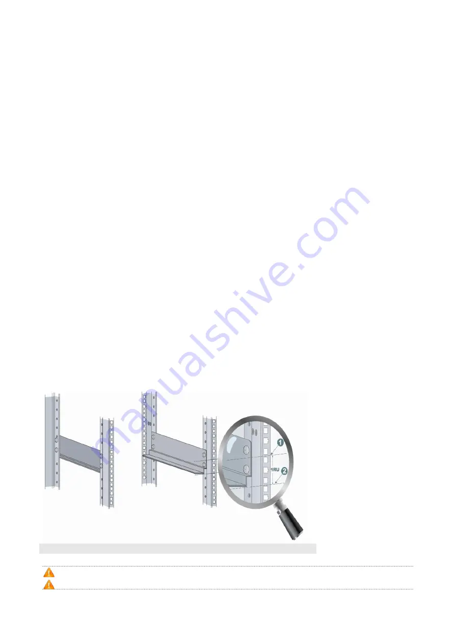
Before installing a guide rail, you need to have some knowledge of standard 19-inch cabinets of IEC60297. The height of 
standard cabinets is measured in Rack Unit (RU, 1 RU = 44.45 mm (1.75 inch)). 1 RU is equal to the height of three holes 
(see Figure 3-1). The hole in the middle is an auxiliary installation hole, and the other holes are standard installation holes. 
Note that the space between neighboring standard installation holes is a little smaller than that between an auxiliary 
installation hole and its neighboring standard installation hole. When installing a guide rail for the RG-WALL1600-X9300 
series, ensure that the plane to carry the chassis should be installed on the plane of delimiters (entire-U delimiter) of the 
two neighboring RUs, as shown in Figure 3-1. 

Figure 3-1 Guide Rail   


Note: 

1 and 2 representing 1 RU delimiters 


Before installing a guide rail, confirm that the weight capacity of the guide rail meets requirements. 


Considering a variety of guide rails, guide rail appearance and installation methods depend on the actual situation. 

Summary of Contents for RG-WALL1600-X9300

Page 1: ...RG WALL1600 X9300 Next Generation Firewall Hardware Installation and Reference Guide V1 3...

Page 2: ...or by any means without the prior written consent of Ruijie Networks is prohibited Exemption Statement This document is provided as is The contents of this document are subject to change without any n...

Page 3: ...s and concepts Obtaining Technical Assistance Ruijie Networks Website https www ruijienetworks com Technical Support Website https ruijienetworks com support Case Portal http caseportal ruijienetworks...

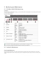
Page 4: ...o 240 VAC 47 63 Hz Maximum Current 110V 8A 220V 4A Power Consumption Average Max 338 W 406 W Heat Dissipation 1 385 BTU h The RG WALL1600 X9300 is an A class product and may cause radio disturbance to...

Page 5: ...rt 4 MGMT 1 2 RJ 45 It is applied to Web management on PC The default IP address of MGMT interface1 is 192 168 1 200 5 POWER Power 100 240V AC 8 4A 50 60Hz 6 SFP Port 1 16 SFP Gigabit fiber port It is...

Page 6: ...room before installation First cut off the power supply in case of an accident Be sure to make a careful check before you shut down the power supply Do not place the equipment in a damp wet location D...

Page 7: ...t meet the following requirements 2 2 1 Rack Mounting Requirements To mount the RG WALL1600 X9300 in a cabinet verify that the cabinet meets the following conditions Install the device in an open cabi...

Page 8: ...rence may occur more easily when the relative humidity is low not only affecting the use life of the equipment but also causing communication faults The following table shows the requirements for the...

Page 9: ...from the electric grid The working ground of the device should be properly separated and kept as far as possible from the grounding device of the power equipment or the anti lightning grounding devic...

Page 10: ...ation location networking mode power supply and wiring before installation Verify the following before installation The installation location is of a good air flow The installation location meets the...

Page 11: ...Installation Steps 1 Plan the available space before installing the cabinet You must reserve sufficient space for front and back doors for maintenance 2 Mount and fasten the cabinet at the designed l...

Page 12: ...e Use screws to fasten them to the fastening bracket of the cabinet After fastened the equipment should be stable and still in the cabinet 3 5 Connecting the AC Power Supply to the Power Module Connec...

Page 13: ...e front back cabinet doors can be closed Verify that the cabinet has been fastened completely and does not move or tilt Verify that the equipment has been installed in the cabinet and all the cables h...

Page 14: ...as much as its diameter Installing and Removing 40 Gigabit QSFP Module The 40G QSFP module is hot swappable input output device that plugs into a 40 Gigabit Ethernet QSFP port through fiber or copper...

Page 15: ...or from the SFP port on the firewall During the operation make sure that the cable s bending radius is no less than eight times as much as its diameter Do not push or pull too strongly If replacement...

Page 16: ...meters Start the PC and run the terminal simulation program on the PC such as Terminal on Windows 3 1 or HyperTerminal on Windows 95 98 NT 2000 XP Set terminal parameters The parameters are as follows...

Page 17: ...parameters click OK Now many PCs do not have Console ports and systems do not support hyperterminals Therefore Console to USB cables and terminal emulators e g SecureCRT are needed Parameter Settings...

Page 18: ...y check none stop bit 1 and no flow control 1 Choose File Connect click New Session in the displayed list and select Serial in the Protocol dropdown list Click Next and the following interface will be...

Page 19: ...llowing interface will be displayed Figure 4 7 4 Click Finish and the following interface will be displayed Figure 4 8 4 2 Power on Startup Checking Before Power on The device is properly grounded The...

Page 20: ...y started the parameters are already configured Checking After Power on Recommended After power on you are recommended to perform the following checks to ensure the normal operation of follow up confi...

Page 21: ...king The Ethernet port is receiving transmitting data Off The Ethernet port is down 5 Ethernet Port Rate Green The port is up at 1000 Mbps Yellow The port is up at 100 Mbps Off The port is up at 10 Mb...

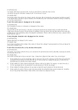
Page 22: ...Troubleshooting Procedures Fault 1 The system login password is lost Fault Description The login password is forgotten or lost and so it is not possible to configure the data Troubleshooting Please c...

Page 23: ...d on the console Troubleshooting Such problem is related to the settings of the serial port Check if the settings of such parameters as the baud rate are the same as the settings above Fault 5 The lin...

Page 24: ...pairs of the 1000BASE T In addition to the above cables the 100BASE TX 10BASE T can also use up to 100m of 10Mbps 100 ohm Category 3 4 5 cables and 100Mbps 100 ohm Category 5 cables Figure A 2 shows t...

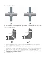
Page 25: ...s type of cables that often bend or suffer removal insertion should be greater than 10 times its diameter Requirement for the minimum fiber bend radius The diameter of a fiber tray to hold fibers cann...

Page 26: ...ect device running or cause device damage or cable damage during commissioning 220V and 48V power cords cannot be bundled on the guide rails of moving parts The power cables connecting moving parts su...

Page 27: ...bunches with cables in cable bunches clean and straight Binding by using buckles should be performed according to Table B 1 Cable Bunch Diameter mm Binding space mm 10 80 150 10 30 150 200 30 200 300...

Reviews: