background image

14

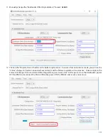
11.  Manually change the “Bootloader Offset (Byte Address)” to read:  

0xA00

12.  Click on the “Program Device” button in the bottom right corner.  If a successful connection is made, you will see the 

“Status” change to “Device Connected Successfully” and the firmware update will commence.  Once complete, the 

Status will change to “Disconnected after Programming was Successful.”  At this point, close the bootloader, power 

OFF the RNDAC, disconnect the Micro USB cable, power ON the RNDAC and resume normal use.

Summary of Contents for Fidelice RNDAC

Page 1: ...Operations Manual Serial Number Fidelice RNDAC Precision Digital to Analog Converter...

Page 2: ...ted Consult the dealer or an experienced radio TV technician for help CAUTION Changes or modifications to this device not expressly approved by Rupert Neve Designs LLC could void the user s authority...

Page 3: ...uction Block Diagram Front Panel Rear Panel RNDAC Features USB Audio Setup DSD Playback Digital Filter Options Micro USB Firmware Update Specifications Frequency Response Graphs Limited Warranty 1 1 2...

Page 4: ...low distortion analog signal paths that compliment the RNDAC s Digital to Analog Conversion ultimately providing the listener with true high fidelity reproduction 1 RNDAC Block Diagram A R 2 3 XLR BA...

Page 5: ...d when button is illuminated Analog RCA Unbalanced XLR Balanced Digital S PDIF Coaxial S PDIF Optical USB Sample Rate LED Indication LED indication for digital source sample rate PCM Playback 44 1k 48...

Page 6: ...e Output Nominal Output Level 10dBV RCA ANALOG INPUT Class A Unbalanced Stereo Line Input Nominal Input Level 10dBV 4 10 Toggles XLR input level standard UP 4dBu Nominal default DOWN 10dBV Nominal COA...

Page 7: ...ne amplifier performance and provide the best possible listening experience Source Select The front panel SOURCE selection buttons allow the user to randomly select between the five 5 available RNDAC...

Page 8: ...com for more information RCA Analog Input The stereo RCA analog inputs are available to connect to other common RCA output sources such as CD players home entertainment receivers computer sound cards...

Page 9: ...feature is INACTIVE The dip switch must be flipped to the DOWN position to make the DAC feature ACTIVE The RNDAC DEFAULT setting is all dip switches in the UP position While we spent a significant amo...

Page 10: ...ge 2 Once the driver download is finished run rndac_driver exe to install the drivers on your PC 3 After installation is complete Windows should notify that the driver is Ready to Use 4 Click Finish T...

Page 11: ...output this data In this case the user can manually adjust the RNDAC sample rate Windows and Mac OS have different methods Sample Rate Configuration Windows 1 Navigate to Windows Sound Preferences Co...

Page 12: ...Configuration Mac 1 Navigate to Go Utilities on the Mac Finder Menu Bar or press Shift Command U Double click on Audio MIDI Setup The Audio Devices Window should pop up if not press Command 1 to unhi...

Page 13: ...dip switch is in the DOWN position There are three separate filter options Slow Roll Off Super Slow Roll Off and Sharp Roll Off see frequency response graphs on pg 19 20 In addition to three filter mo...

Page 14: ...ut DO NOT power ON the RNDAC 3 BEFORE turning on the RNDAC open the Device Manager in Windows or System Report for Mac OS Locate Ports COM LPT in the device manager list and click on the drop down arr...

Page 15: ...the RNDAC Bootloader UnifiedHost 0 1 14 A window will pop up 7 Click on the Device Architecture drop down box and select 8 bit Once 8 bit architecture is selected the Bootload er window will refresh...

Page 16: ...10 Click on the COM Port drop down menu Select the COM Port Number you referenced in Step 4 in this example COM7 Next click on the Bits per second drop down menu and select 57600 After both of these...

Page 17: ...ccessful connection is made you will see the Status change to Device Connected Successfully and the firmware update will commence Once complete the Status will change to Disconnected after Programming...

Page 18: ...22 kHz BW 0 0003 typical Balanced Input to Unbalanced Headphone Output ZSOURCE 40 Balanced Input Impedance 10 k Output Impedance 0 01 Noise Max Volume 10 Hz 22 kHz BW 98 2 dBV typical Frequency Respon...

Page 19: ...0 006 typical Coaxial S PDIF Input to Balanced Headphone Output 192 kHz SR with Slow Roll Off Filter Output Impedance 0 02 Noise Max Volume 10 Hz 22 kHz BW 89 2 dBV typical Frequency Response 5 Hz to...

Page 20: ...Analog Frequency Response Balanced In to Balanced Out ZSOURCE 40 Balanced 30 ft Output XLR Analog Frequency Response Unbalanced In to Unbalanced Out ZSOURCE 470 Unbalanced 17...

Page 21: ...Analog Frequency Response Balanced In to Unbalanced Headphone Out ZSOURCE 40 Bal ZLOAD 16 Digital Filter Frequency Response 192kHz SR COAX S PDIF In to Balanced Out 18...

Page 22: ...Digital Filter Frequency Response 192kHz SR COAX S PDIF In to Unbalanced Out Digital Filter Frequency Response 192kHz SR COAX S PDIF In to Unbalanced Headphone Out 19...

Page 23: ...Digital Filter Frequency Response 192kHz SR COAX S PDIF In to Balanced Headphone Out ZLOAD 16 20 192kHz SR COAX S PDIF In Unbalanced vs Balanced Headphone Out Frequency Response...

Page 24: ...SEXPRESS LIMITEDWARRANTYISINLIEUOFALLOTHERWARRANTIES EXPRESS OR IMPLIED TO THE EXTEND ALLOWED UNDER APPLICABLE STATE LAW IN NO EVENT SHALL RUPERT NEVE DESIGNS BE LIABLE FOR ANY SPECIAL INCIDENTAL OR C...

Reviews: