background image

4

36

30

24

18

12

6 0dB 66

60

54

48

42

LF PEAK

8K

EQ IN

MID HI Q

HF PEAK

MIC / DI

SILK

VU SELECT

PEAK

RED


/


BLUE

48V

HPF

LINK

GND LIFT

COMP IN

PRE EQ

FAST

S/C

INSERT

MID FREQ

LOW FREQ

HF

MID

LF

TEXTURE

TRIM

MIC GAIN

DI

THRU

HPF FREQ

SIGNAL

THRESHOLD

RATIO

BLEND %

TIMING

HPF to S/C

GAIN dB

OUTPUT

REDUCTION

SHELFORD

C H A N N E L

RUPERT NEVE DESIGNS

3K5

1K8

900

400

220

7K5

220

100

60

35

6:1

4:1

3:1

2:1

1.5:1

8:1

SLOW

MS

MED

MF

FAST

AUTO

LINE

16K

0dB

-6

+6

100

20Hz 250Hz

0

-15

+15

0

-15

+15

0

-15

+15

-2

-25

+20

+12

-18

+6

0

-6

+20

50

0

100


MIN

MAX

Thru

Passive loop out of
 the DI input signal

Trim

Provides continuous 

gain adjustment, 

over a range of +/– 6 dB.

Mic/DI/Line

Selects the Mic

/ DI input or

Line input


EQ In

Engages all

frequency

bands except

the HPF

Signal

Green indicates
signal present.
Red indicates
near clipping.

HPF Freq

Selects frequency

where the 12 dB per octave

 high-pass filter

begins to roll off

low frequency signals.

HPF

Engages high-pass filter

Mid Hi Q

When pressed, reduces

Q width of all mid

band frequencies.

Mid Freq

6 position select the
center frequency of 
the mid band EQ stage.

8k/16k

With switch out, 
center or corner 
frequency of high
band is 8 kHz. When
pressed, center or
corner frequency
changes to 16 kHz. 

Low Freq

4 position switch
selects corner or

 center frequencies for

the low band EQ.

DI

Jack for direct injection

(DI) or instrument inputs

GND Lift

Separates the

direct connection

from audio signal

 ground to chassis earth.

Mic Gain

12-position rotary switch

controls gain from 

0 to 66 dB in 6 dB steps.

48V

Engages phantom power
on the microphone input.

Phase

Inverts the phase (polarity)
of the signal path.
Illuminates when engaged. 

LF

Adjusts up to 15 dB of

boost or cut at selected

low frequencies.

Mid

Adjusts up to 15 dB of

boost or cut at selected

mid frequencies.

LF Peak

Selects between

Shelf mode

(button out)

or Peak mode

(button in)

HF Peak

Selects between

Shelf mode

(button out)

or Peak mode

(button in)

HF

Adjusts up to 15 dB of boost

          or cut at selected high frequencies.

AC Input

IEC input jack for
100-240V AC.

Chassis Ground Lift

Separates the direct connection

from audio signal ground to chassis earth.

Line Output

Transformer coupled, fully balanced
and floating. Can output signals
up to +26.5dBU. 
1= GND  2= Hot  3= Cold

VU

Illuminated meter/power indicator

VU

MIC IN

LINE IN

-6dB LINE OUT

LINE OUT

SIDE CHAIN

COMPRESSOR

SEND

LINK

RETURN

GND

LIFT

POWER

100-240 VAC

50/60Hz

35 Watts

CAUTION

Risk of Electric Shock

Disconnect from outlet

before removing cover

Rupert Neve Designs, LLC
Model 5035

MADE IN USA

5024-XXXXXX

Rupert Neve Designs, LLC

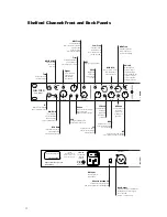
Shelford Channel: Front and Back Panels

Summary of Contents for SHELFORD CHANNEL

Page 1: ...Operations Manual SHELFORD CHANNEL Transformer Gain Mic Pre amp Inductor EQ Diode Bridge Compressor...

Page 2: ...cted Consult the dealer or an experienced radio TV technician for help CAUTION Changes or modifications to this device not expressly approved by Rupert Neve Designs LLC could void the user s authority...

Page 3: ...igns with new levels of versatility delivering what can only be described as the combined essence of fifty years of Rupert Neve s designs Everyone at Rupert Neve Designs hopes that you enjoy using thi...

Page 4: ...Low Freq 4 position switch selects corner or center frequencies for the low band EQ DI Jack for direct injection DI or instrument inputs GND Lift Separates the direct connection from audio signal grou...

Page 5: ...handle signals up to 8dBU 1 GND 2 Hot 3 Cold Blend Controls the mix of the compressed and uncompressed signals Texture Continuously variable detented control for Silk Red and Blue modes Allows fine t...

Page 6: ...years for Rupert Neve This new custom designed input transformer along with its careful integration with the surrounding circuitry is critical to the Shelford Channel s bold and instantly recognizabl...

Page 7: ...ife in a way that other effects cannot Another advantage of this output stage versus vintage modules is the addition of the variable Silk circuitry which allows complete control over the harmonic cont...

Page 8: ...e the Inductor EQ and Transformer Gain microphone preamp the Diode Bridge Compressor in the Shelford Channel is based on the same topologies found in Rupert s vintage designs such as the 2254 but it e...

Page 9: ...mic harmonic content By manipulating input levels and the blend control the diode bridge circuit can be used as an automatic tone shaping tool even with minimal gain reduction INPUT CONTROLS DI and Th...

Page 10: ...er or they will not function Phase This push button switch inverts the polarity of the signal path It illuminates when engaged The symbol is often used to denote opposite polarity HPF The HPF switch e...

Page 11: ...frequency band changes to peak mode with a bell shaped boost or cut curve Utilizing the LF PEAK button and LF FREQ rotary switch an engineer has 8 tonal variations of EQ shapes to finesse the bottom...

Page 12: ...F Adjusts up to 15 dB of boost or cut at selected high frequencies COMPRESSOR LIMITER CONTROLS THE SIDE CHAIN INSERT JACKS These jack pairs are used to fine tune the compressor s operation The audio t...

Page 13: ...ld and Ratio of the compressor it is helpful to utilize the VU meter however one should ultimately rely on their ears and diligent use of the COMP IN Bypass Button for comparison SC Insert This contro...

Page 14: ...ak the HMF if the compressor seems to be affecting transient peaks Blend The blend control allows the user to dial in the desired mix ratio of the uncompressed signal with the compressed signal With t...

Page 15: ...e control the amount of Silk can be changed from essentially absent to even greater levels than could be achieved with vintage products With silk texture engaged the distortion characteristic and harm...

Page 16: ...12 66 Noise Un weighted 22Hz 22kHz source impedance 150 Ohms balanced Main Out unity gain 100 9dBu 6dB Out unity gain 106 6dBu 30dB gain Main Out 91 37dBu 66dB Gain Main Out 64 1dBu Equivalent Input...

Page 17: ...n 10Hz to 110kHz 0 32dB 120kHz Maximum Output Level 26dBu 16Hz to 20kHz Total Harmonic Distortion and Noise with SILK engaged RED TEXTURE min 100Hz 20dBu input level no load 0 0131 mostly 3rd harmonic...

Page 18: ...Time Constants Measurements taken represent full range achievable between 1 5 1 Ratio and 8 1 Ratio setting 0 dBu I P 1kHz Burst Tone used for all recorded measurements Fast TC1 Attack 180 S 1 8mS Re...

Page 19: ...0 12 14 16 18 d B u 10 100k 20 50 100 200 500 1k 2k 5k 10k 20k 50k Hz Audio Precision 07 14 16 16 34 46 FreqResp_LoFreqShelf at27 Color Sweep Trace Line Style Thick Data Axis Comment 1 1 Cyan Solid 3...

Page 20: ...0 22 5 d B u 10 200k 20 50 100 200 500 1k 2k 5k 10k 20k 50k 100k Hz Audio Precision 07 01 16 13 29 57 FreqResp_LoQMidBandEQCut at27 Color Sweep Trace Line Style Thick Data Axis Comment 1 1 Cyan Solid...

Page 21: ...0k 20 50 100 200 500 1k 2k 5k 10k 20k 50k 100k Hz Audio Precision 07 01 16 13 46 06 FreqResp_HiQMidBandEQCut at27 Color Sweep Trace Line Style Thick Data Axis Comment 1 1 Cyan Solid 3 Anlr Level A Lef...

Page 22: ...5 15 17 5 20 d B u 10 200k 20 50 100 200 500 1k 2k 5k 10k 20k 50k 100k Hz Audio Precision 07 14 16 17 01 58 FreqResp_HiFreqShelf at27 Color Sweep Trace Line Style Thick Data Axis Comment 1 1 Cyan Sol...

Page 23: ...6 14 12 10 8 6 4 2 0 2 4 d B u 20 200k 50 100 200 500 1k 2k 5k 10k 20k 50k 100k Hz Audio Precision 07 14 16 16 50 54 FreqResp_Silk at27 Color Sweep Trace Line Style Thick Data Axis Comment 1 1 Cyan So...

Page 24: ...formed THIS EXPRESS LIMITED WARRANTY IS IN LIEU OF ALL OTHER WARRANTIES EXPRESS OR IMPLIED TO THE EXTEND ALLOWED UNDER APPLICABLE STATE LAW IN NO EVENT SHALL RUPERT NEVE DESIGNS BE LIABLE FOR ANY SPEC...

Reviews: