13
TROUBLESHOOTING AND SOLUTION
EFFECTS
CAUSES
SOLUTIONS
The turbine will not start
No power
Check the connection at the electric panel
Power supply cable, switch
Call an authorised service centre
or motor faulty
The turbine will not start
Faulty electronics
Call an authorised service centre
in automatic
or microswitch
Poor suction capacity
Dust bag full
Replace the bag
One of the pipes or accessories is blocked
Check hoses and accessories
Filter cleaning system fault
Check air pressure.
Blocked filter
Call an authorised service centre
Dust leaks from the turbine
Cartridge filter ruptured
Switch off the turbine immediately
discharge
and call an authorised service centre
Compressed air does not arrive at the distributor
Inlet coupling not connected properly
Check the connection
Adjusting the regulator
Regulator faulty or air leak in the system
Call an authorised service centre
change in the pressure gauge reading
in the system
GENERAL MAINTENANCE
Ordinary maintenance (by the user)
- Check the condition of the compressed air feed hoses and relative
connections;
- check the condition of the dust suction pipes;
- periodically replace the dust bag;
- drain the condensate from the pressure regulator collection tray (4B)
daily by rotating screw anticlockwise.
The dust bag (21) is housed in a container (8) located inside a com-
partment (9) .
Each morning, prior to starting the turbine, visually inspect the correct
positioning of the dust bag and the contents, which must not be
more than 3/4 of the capacity of the bag itself.
Replacing the dust bag:
- Switch off the turbine completely by turn the knob (30) to OFF to
switch the shut down the machine.
- Open door (8) and the filter housing will lift automatically to free the
dust bag. Extract the container (21) and free the dust bag from the
plastic ring. Remove the bag containing the dust and seal it with a
clip. See the sequence in Fig. 6-7-8-9-10.
Hook the bag onto the plastic ring and fix it in position in its housing
(Fig. 6) using the elastic. Tilt the bag so that the pressure balancing
holes (Fig. 8) are free. Place the bag in the container ensuring that it
is well spread on the bottom of the container. Place all the
components inside the compartment and close the door (8-9).
The utmost care must be taken when carrying out these operations to
prevent dust from being allowed to enter the environment. Wear a
dust mask.
The sealed bag must be delivered to an authorised disposal centre.
Filter cleaning system
When the motor is switched on, in either automatic or manual mode,
the filter cleaning system will carry out a periodic filter cleaning cycle
of duration 3 seconds. This system allows the filter cartridge to
operate efficiently. It is also possible to perform manual cleaning
cycles by pressing button (45).
Extraordinary maintenance (by the service centre)
Extraordinary maintenance and the repairs listed below must be
carried out by specialised electronic personnel authorised by RUPES
Spa Before gaining access to the internal parts of the turbine,
disconnect the unit from the mains electricity supply. Lock the eternal
panel using padlock to prevent accidental start-up. The key to the
padlock must be kept by the person responsible for factory safety.
RUPES Spa. will not be held responsible for direct or indirect
damages resulting from non-compliance with the requirements of this
manual.
Suction pump (13)
The unit does not require maintenance if used continuously for 8
hours a day. Replace the bearings every 20,000 hours. Check the
conditions of the electric cables every 6 months and verify that the
cooling grid is cleaned.
Hoses (46)
Check the tightness of the clips every 6 months.
Filter (17)
Check every 6 months. Replace every 2,500 hours.
Complete pneumatic plant
Check for leaks every 6 months.
Electronic panel (23)
Check the tightening of all clamps every 6 moths, clean all the
internal components with
dry and low pressure compressed air
, and
check the working conditions of the thermal protection device.
Turbine structure
During the periodic inspections, check the tightness of all bolts.
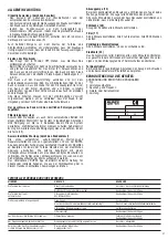
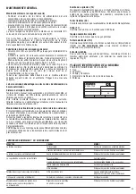
TOOL IDENTIFICATION PLATE
POSITION AND MEANING OF INFORMATION
1. Type.
2. Absorption.
3. Voltage and frequency.
4. Tool code or serial number.
5. Power.
4
5
3
2
1
A
V. Hz.
MILANO - ITALY


