


6
To turn the polisher off, release the lever or, if locked in ON
position, push the lever to release the lock button.
ELECTRONIC SPEED CONTROL
The polisher electronic speed control supply the following fea-
tures.
Speed compensation
In case of overloading the polisher, the electronic speed control
will compensate and maintain the selected speed till a safe level.
Exceeding this overload level may result in strong vibrations and
tool overtemperature.
Starting acceleration ramp
To avoid kickback effect and compound splattering, the
electronic speed control always supply a smooth starting
acceleration ramp when the tool is turned on.
Accidental re-start protection
In case of a sudden lack of main power supply, the electronic
speed control prevents the re-start after the power supply
restoring if the main switch is turned on. The polisher must be
turned off and on again pushing the lever of the switch (2)
toward the body of the tool.
OPERATION
INTENDED USE
MOTOR
Be sure your power supply agrees with the voltage marked on
the nameplate. 120 Volts AC 60Hz means alternating current
only. Voltage decrease of more than 10% will cause loss of
power and overheating.
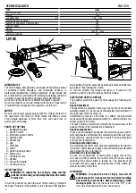
PARTS OF THE TOOL
ON/OFF SWITCH
To turn the polisher on, push the lever of the switch (2) towards
the body of the tool; if the polisher is to be locked in ON position,
press button ( ) at the same time and keep it pressed while
releasing lever, thus locking the switch.
WARNING: To reduce the risk of injury, make sure the
polisher is not resting on the workpiece when the switch
is turned on.
WARNING: To reduce the risk of injury, turn unit off and
disconnect it from power source before installing and
removing accessories, before adjusting or when making
repairs. Be sure the switch is in the “OFF” position. An
accidental start-up can cause injury
WARNING: Never modify any parts of the power tool.
Damage or personal injury could result.
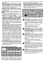
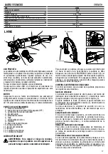
MODEL
LK900E
165
150
250÷560
2,70
•
VOLTAGE
120 V AC - 60 Hz
ABSORBED CURRENT
TECHNICAL DATA
ENGLISH
LK900E
5
900
7 A
/ II
Ø POLISHING FOAM mm
Ø BACKING PAD mm
Ø ORBIT mm
POWER
R.P.M.
WEIGHT
ELECTRONIC SPEED CONTROL
INSULATION CLASS
7
5
2
6
3
1
4
8
OFF
ON
Speed Adjustment
ON
OFF
6
3
2
1
5
4
7
8
9
9
INTENDED USE
The LH19E heavy-duty polishers is designed for polishing painted
or unfinished metal, fiberglass, and composite surfaces in
professional applications. Common examples of use include but
are not limited to: auto/marine/RV/motorcycle detailing and finish
correction, boat construction and repair, and metal finishing.
Do not use in the presence of flammable liquids or gases.
Do not let children come into contact with the tool. Supervision
is required when inexperienced operators use this tool.
MOTOR
Be sure your power supply agrees with the voltage marked on
the nameplate. 120 Volts AC 60Hz means alternating current
only. Voltage decrease of more than 10% will cause loss of
power and overheating.
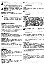
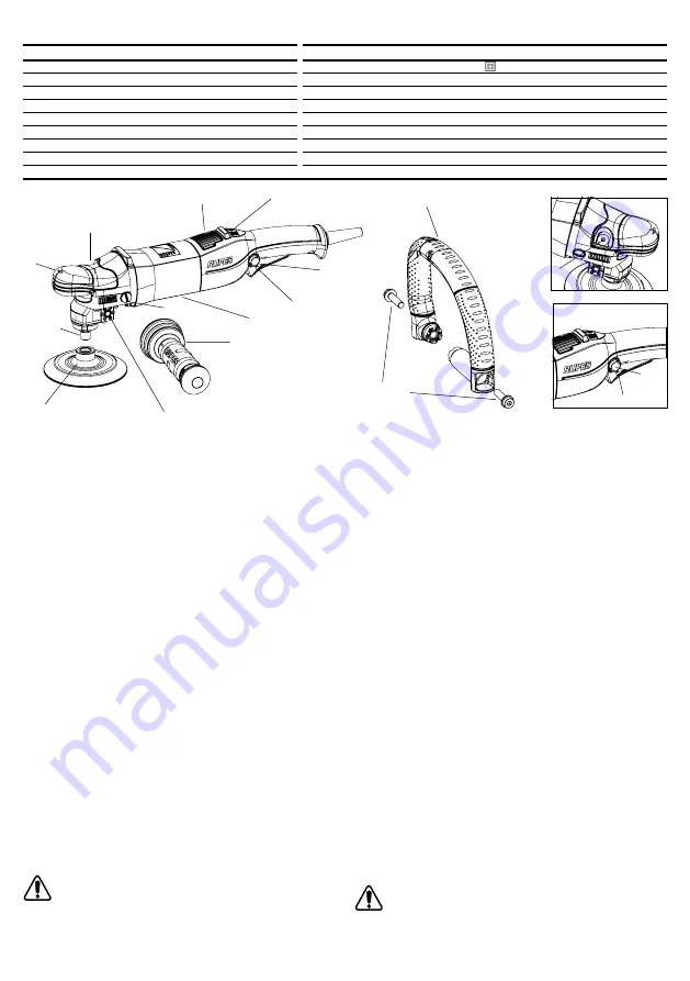
PARTS OF THE TOOL
1 - Identification plate
2 - ON/OFF switch
3 - Electronic speed control
4 - Spindle shaft
5 - Handle site
6 - Cap
7 - Plate pad
8 - Srews
9 - Switch locking botton
10 - Botton lock
11 - Ventilator motor
12 - Handle
13 - Scews for handle
14 - Locking screws
ON/OFF SWITCH
WARNING: To reduce the risk of injury, make sure the
polisher is not resting on the workpiece when the switch
is turned on.
To turn the polisher on, push the lever of the switch (2) towards
the body of the tool; if the polisher is to be locked in ON position,
press button (9) at the same time and keep it pressed while rele-
asing lever, thus locking the switch.
To turn the polisher off, release the lever or, if locked in ON
position, push the lever to release the lock button.
ELECTRONIC SPEED CONTROL
The polisher electronic speed control supply the following fe-
atures.
Speed Adjustment
The speed can be adjusted in two ways: by means of the variable
actuation switch (2), by means of the adjustment wheel fitted on
the upper part of the machine (3).
Adjustment by means of the wheel (3) affects the adjustment
made using the variable actuation switch (2), determining the ma-
ximum speed of the motor.
The speed must be selected according to the characteristics of the
pads and those of the material to be machined.
Speed compensation
In case of overloading the polisher, the electronic speed control
will compensate and maintain the selected speed till a safe level.
Exceeding this overload level may result in strong vibrations
and tool overtemperature.
Starting acceleration ramp
To avoid kickback effect and compound splattering, the electro-
nic speed control always supply a smooth starting acceleration
ramp when the tool is turned on.
Accidental re-start protection
In case of a sudden lack of main power supply, the electro-
nic speed control prevents the re-start after the power supply
restoring if the main switch is turned on. The polisher must
be turned off and on again pushing the lever of the switch (2)
toward the body of the tool.
OPERATION
WARNING: To reduce the risk of injury, turn unit off
and disconnect it from power source before installing
and removing accessories, before adjusting or when
making repairs. Be sure the switch is in the “OFF” posi-
tion. An accidental start-up can cause injury
6
2
9
3
11
1
5
8
14
4
10
7
LH19E
12 (
optional)
13 (
optional)
TYPE
INSULATION CLASS
POWER
W
n NOMINAL RPM
/min
ELECTRONIC SPEED CONTROL
BUFFER PAD AND BUFFER DIAMETER MAX
SPINDLE THREAD
WEIGHT Kg
VOLTAGE
ABSORBED CURRENT
LH19E
/ II
1200
450 ÷ 1700
YES
200
5/8’’
2,25
120 V AC – 60Hz
8.5 A
10
2
9
Summary of Contents for LH19E
Page 2: ......


