background image

8

GENERAL WARNINGS

The safety and accident prevention instructions are reported in the
“SAFETY INSTRUCTION” booklet which forms an integral part of
these documents. This OPERATING INSTRUCTION MANUAL
indicates the additional information required specifically for use of
the tool.

CORRECT USAGE

This tool is designed to be used as a sander.  
Read all the warnings, instructions, indications provided on
drawings and specifications supplied with this tool.

Failure to comply

with all the instructions provided below may cause serious injuries.

This tool is not intended to be used for metal brushing, polishing
and cutting operations. 

The use of this tool for unintended applications

may cause hazards and injuries to people.

NOISE / MEAN ACCELERATION VALUE

The noise level produced and the mean quadratic acceleration value
are measured according to regulation 

UNI EN ISO 15744 -

EN ISO 28927.

(*) Vibration level defined by previous regulation EN ISO 8662.

Displayed emission values are comparative and are to be employed
for a provisional assessment of the operator’s risk exposure during
the work period. Appropriate evaluation of work period must also
include tool’s idle and stop periods. These emission values represent
the tool’s main applications. If the tool is used for other applications,
with other accessories, or if it does not undergo regular maintenance,
emission values can significantly increase during operations.

                Sound pressure level  Uncertainty   Sound power level  

                          [dB(A)]               [dB(A)]          [dB(A)]

                            LpA                       K                 LwA

RH223-RH253       73                        3                  84
RH226-RH256       75                        3                  86
RH229-RH259       76                        3                  87
RH223A-RH253A   72                        3                  83
RH226A-RH256A   74                        3                  85
RH229A-RH259A   75                        3                  86
RH223T-RH253T    72                        3                  83
RH226T-RH256T    74                        3                  85
RH229T-RH259T    75                        3                  86

                            3 axis          Uncertainty             1 axis(*)

                              LpA                   K                        LwA

RH223-RH253       2,80                0,20                    <2,50
RH226-RH256       3,00                0,30                     2,60
RH229-RH259       3,20                0,35                     2,80
RH223A-RH253A   2,80                0,20                    <2,50
RH226A-RH256A   3,00                0,30                     2,60
RH229A-RH259A   3,20                0,35                     2,80
RH223T-RH253T    2,80                0,20                    <2,50
RH226T-RH256T    3,00                0,30                     2,60
RH229T-RH259T    3,20                0,35                     2,80

Vibration level [m/s

2

]

PARTS OF THE TOOL

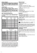
1. Identification plate
2. Compressed air on/off lever
3. Speed control

4. Tool body

5. Compressed air connection with 1/4” thread

6. 25 / 29 mm. int. Ø suction pipe connection (SERIES RH..A and RH..T)

7. Silencer
8. Suction shroud (SERIES RH..A and RH..T)
9. Backing pad

10. Back-up pad screw
11. Lubricating oil
12. Back- up pad spanner
13. Filter unit: cartridge (a) and filter holder (b) (RH..T SERIES) 
14. Dust suction pipe (SERIES RH..T)

STARTING UP

Before starting-up the tool, ensure that:
- the packaging is complete and does not show signs of having been

damaged during storage or transport;

- the available compressed air production and distribution plant is

capable of satisfying the requirements reported on the tool’s
identification plate.

ASSEMBLING THE TOOL

Assemble the compressed air connection (not supplied) by screwing
it into its seat (5).

Ensure that, when compressed air is connected, the
pneumatic tool activation switch (2) is disconnected.

For the compressed air supply a compressor complying with the
technical characteristics listed in the tool data label must be used.
All instruments, connection hoses and pipes must be suitable for
the corresponding pressure and quantity of air necessary.

COMPRESSED AIR CONNECTION

(NOT SUPPLIED)

The tool is supplied without the compressed air connection; the user
can use either a quick release coupling or hose type connection
according to his needs, as long as they have an hole of air passing
mm. 8. 
In the latter case the air line must be fixed to the nozzle by a hose
clip.

STARTING AND STOPPING

- Starting: push the control lever (2) forward towards the body of

the tool and keep it pressed;

- Stopping: release the control lever.

Summary of Contents for RH223

Page 1: ...259T RH223 RH226 RH229 RH223A RH226A RH229A RH223T RH226T RH229T IT Levigatrici rotorbitali pneumatiche GB Random orbital pneumatic sanders 2 6 Via Marconi 3A 20080 VERMEZZO Mi Italy Tel 02 946941 Fax 02 94941040 e mail info_rupes rupes it web www rupes com ...

Page 2: ... orbita n0 Velocità a vuoto Velocità del rotante min Giri al minuto Velocità Freccia Agire in direzione indiata dal senso della freccia 2 DATI TECNICI Levigatrici rotorbitali pneumatiche RH223 RH253 RH226 RH256 RH229 RH259 Pressione max di entrata bar PSI 6 2 90 6 2 90 6 2 90 Consumo aria l min 340 340 340 Giri a vuoto n0 min 0 11 000 0 11 000 0 11 000 Ø orbita mm 3 6 9 Ø platorello mm 125 150 125...

Page 3: ...O CENTRALIZZATO CENTRALIZZATO Massa Kg 0 800 0 800 0 800 DATI TECNICI Levigatrici rotorbitali pneumatiche RH223T RH253T RH226T RH256T RH229T RH259T Pressione max di entrata bar PSI 6 2 90 6 2 90 6 2 90 Consumo aria l min 340 340 340 Giri a vuoto n0 min 0 11 000 0 11 000 0 11 000 Ø orbita mm 3 6 9 Ø platorello mm 125 150 125 150 125 150 Sistema di aspirazione AUTOASPIRANTE AUTOASPIRANTE AUTOASPIRAN...

Page 4: ... 86 Su 3 assi Incertezza Su 1 asse LpA K LwA RH223 RH253 2 80 0 20 2 50 RH226 RH256 3 00 0 30 2 60 RH229 RH259 3 20 0 35 2 80 RH223A RH253A 2 80 0 20 2 50 RH226A RH256A 3 00 0 30 2 60 RH229A RH259A 3 20 0 35 2 80 RH223T RH253T 2 80 0 20 2 50 RH226T RH256T 3 00 0 30 2 60 RH229T RH259T 3 20 0 35 2 80 Livello di vibrazioni m s2 PARTI DELLA MACCHINA 1 Etichetta di identificazione 2 Leva di comando imm...

Page 5: ...zioni di manutenzione e riparazione devono essere eseguite da personale qualificato A fine lavoro od in caso di necessità spolverare con getto di aria compressa il corpo macchina MANUTENZIONE ORDINARIA Lubrificare periodicamente ogni 50 ore di lavoro la macchina inserendo 2 3 gocce d olio per uso specifico 11 nell attacco aria compressa dell utensile tenendo lo stesso in posizione verticale con l ...

Page 6: ...tion or reciprocation per minute Revolutions strokes surface speed orbits per minute Arrow Action in the direction of arrow TECHNICAL DATA Random orbital pneumatic sanders RH223 RH253 RH226 RH256 RH229 RH259 Max working pressure bar PSI 6 2 90 6 2 90 6 2 90 Air consumption l min 340 340 340 Rpm n0 min 0 11 000 0 11 000 0 11 000 Ø orbit mm 3 6 9 Ø pad mm 125 150 125 150 125 150 Extraction system NO...

Page 7: ...LIZED CENTRALIZED CENTRALIZED Weight Kg 0 800 0 800 0 800 TECHNICAL DATA Random orbital pneumatic sanders RH223T RH253T RH226T RH256T RH229T RH259T Max working pressure bar PSI 6 2 90 6 2 90 6 2 90 Air consumption l min 340 340 340 Rpm n0 min 0 11 000 0 11 000 0 11 000 Ø orbit mm 3 6 9 Ø pad mm 125 150 125 150 125 150 Extraction system SELF VACUUM SELF VACUUM SELF VACUUM Weight Kg 0 800 0 800 0 80...

Page 8: ...3 RH253 2 80 0 20 2 50 RH226 RH256 3 00 0 30 2 60 RH229 RH259 3 20 0 35 2 80 RH223A RH253A 2 80 0 20 2 50 RH226A RH256A 3 00 0 30 2 60 RH229A RH259A 3 20 0 35 2 80 RH223T RH253T 2 80 0 20 2 50 RH226T RH256T 3 00 0 30 2 60 RH229T RH259T 3 20 0 35 2 80 Vibration level m s2 PARTS OF THE TOOL 1 Identification plate 2 Compressed air on off lever 3 Speed control 4 Tool body 5 Compressed air connection w...

Page 9: ... each work session or when required remove any dust from the body of the tool using a jet of compressed air ORDINARY MAINTENANCE Lubricate the machine regularly every 50 hours of operation by inserting 2 3 drops of specific oil 11 into the compressed air connection keeping the device in a vertical position with the connection facing upwards After this operation connect the machine to air compresso...

Page 10: ...RUPES S p A Via Marconi 3A 20080 VERMEZZO Mi Italy Tel 02 946941 Fax 02 94941040 Uff Vendite e assistenza clienti Tel 39 02 94694312 e mail info_rupes rupes it web www rupes com Cod 9 2481 Rev 0 09 2014 ...

Reviews: