background image

49

1.7 Using TrustTrack

This chapter applies only if you are using the TrustTrack fleet management platform 

TrustTrack documentation website: 

https://www.fmsdocumentation.com/


Accessing TrustTrack

TrustTrack can be accessed via the web or using an app. Use the same server domain (typically

track2.ruptela.com) for both web and app. Your login credentials are sent to you by e-mail. If you have

not received them, contact your sales manager.


Accessing TrustTrack via Web

To access TrustTrack via the web, enter your server domain into the browser. Enter your credentials and

click

Sign In

.

Accessing TrustTrack via App

Download the TrustTrack app:

·

iOS

·

Android

Summary of Contents for FM-Eco4 light T

Page 1: ...1 FM Eco4 T User Manual ...

Page 2: ... 1 FM Eco4 T Product Information 6 1 2 FM Eco4 T Technical Information 12 1 3 FM Eco4 T Device Preparation Regular Housing 19 1 4 FM Eco4 T Device Preparation IP67 Housing 22 1 5 FM Eco4 T Device Configuration 26 1 6 FM Eco4 T Installation in Vehicle 42 1 7 Using TrustTrack 49 ...

Page 3: ...2020 04 03 Added Backup Server Updated GNSS module characteristics in Connectivity 1 2 2020 04 27 Added 2G variations of FM Eco4 T series Added Installation Assistant Updated Inserting a SIM card IP67 housing 1 3 2020 08 05 Added RS variations of FM Eco4 T series 1 4 2020 10 16 Added Settings Menu Added Location Accuracy Updated Configuration Menu 1 5 2020 10 26 Updated Certifications Safety Infor...

Page 4: ...ong cables Attention Do not connect the wires marked red power supply and black chassis to the wrong battery poles The device has reverse polarity protection however if connected incorrectly the device will not work Disconnect the device from the power supply before dismounting it To disconnect the device from the power supply you need to disconnect the 12 Pin connector from the device or disconne...

Page 5: ... HDOP Horizontal Dilution of Precision GLONASS Global Navigation Satellite System GMT Greenwich Mean Time GNSS Global Navigation Satellite System GPRS General Packet Radio Service GPS Global Positioning System GSM Global System for Mobile Communications OBD On board Diagnostics LED Light Emitting Diode PCB Printed Circuit Board SMS Short Message Service TCP Transmission Control Protocol UDP User D...

Page 6: ...m articles downloads publication device center Advanced configuration manual https doc ruptela com articles tracking devices publication advanced configurator user manual Firmware and configurator files https doc ruptela com articles downloads publication downloads home Microsoft Framework https dotnet microsoft com download dotnet framework net48 VCOM drivers https doc ruptela com articles downlo...

Page 7: ...enna FM Eco4 light 3G T includes an internal battery and UMTS 3G FM Eco4 3G T includes an internal battery IP67 certified housing and UMTS 3G FM Eco4 3G E T includes an internal battery IP67 certified housing an external GNSS antenna and UMTS 3G FM Eco4 light RS T includes an internal battery and RS232 serial interface FM Eco4 E RS T includes an internal battery IP67 certified housing an external ...

Page 8: ...on LEDs GNSS antenna cable applicability FM Eco4 T FM Eco4 E T FM Eco4 3G T FM Eco4 3G E T FM Eco4 RS T FM Eco4 RS E T FM Eco4 3G RS T FM Eco4 3G RS E T Key Features Real time data from GPS and accelerometer Driver behavior monitoring Eco Drive Driver identification Temperature monitoring Remote ignition blocking ...

Page 9: ... is packed in a cardboard box The package contains the following items 1 The device itself 2 A 12 Pin cable By default no SIM card is provided in the package SIM cards can be obtained from your local phone operator Package Contents IP67 Housing The device is packed in a cardboard box The package contains the following items 1 The device itself ...

Page 10: ... your local phone operator Certifications The FM Eco4 T Series devices have passed quality tests and comply with the following certifications E Mark Certification of Economic Commission for Europe is the European conformity mark issued by the transport sector indicating that the product complies with relevant laws and regulations or directives ...

Page 11: ...ng the equipment off and on the user is encouraged to try to correct the interference by one or more of the following measures Reorient or relocate the receiving antenna Increase the separation between the equipment and receiver Connect the equipment into an outlet on a circuit different from that to which the receiver is connected Consult the dealer or an experienced technician for help Contains ...

Page 12: ...T FM Eco4 E T FM Eco4 E RS T FM Eco4 3G E RS T ANATEL Valid only for 2G variations A certification of radio products for the Brazilian market based on an approval of the local authority Agência Nacional De Telecomunicações Anatel This equipment is not entitled to protection against harmful interference and must not cause interference in duly authorized systems ...

Page 13: ...5 seconds Two devices connected Three times every 5 seconds Three devices connected All Once every 5 seconds Sleep deep sleep mode Device Pinout Variations without RS232 interface Pin Wire color Description BAT VIN Red Power supply 6 12 24V GND Black Ground connection DIN1 Pink Digital input 1 DIN2 Blue Digital input 2 DIN3 White Digital input 3 invertible DIN4 Yellow Digital input 4 invertible AI...

Page 14: ...ta Physical Characteristics 2G variations Dimensions 64 5 x 61 x 22 mm regular housing 95 x 76 4 x 28 8 mm IP67 housing Weight 59 5 g FM Eco4 light T 65 5 g FM Eco4 light T and FM Eco4 light RS T 148 5 g FM Eco4 T 185 5 g FM Eco4 E T and FM Eco4 E RS T Housing material Plastic Connector 12 Pin insulated Configuration interface Mini USB Antenna Internal External FM Eco4 E T and FM Eco4 E RS T only ...

Page 15: ...al Specifications 2G variations FM Eco4 light T Power supply range 6 31 5 V DC Maximum current rating 500 mA 6 V DC Internal battery None Protections Battery short circuit protection not applicable for FM Eco4 light T Reverse polarity protection Overcurrent protection on 1 Wire power line FM Eco4 light T FM Eco4 light RS T FM Eco4 T FM Eco4 E T FM Eco4 E RS T Power supply range 6 31 5 V DC Maximum...

Page 16: ...harged Idle mode 33 mA Active mode peak GSM 135 mA Sleep mode 7 mA Deep sleep mode 4 mA 3G variations Operating battery fully charged Idle mode 33 mA Active mode peak GSM 138 mA Sleep mode 6 3 mA Deep sleep mode 4 mA 2G RS variations Operating battery fully charged Idle mode 33 mA Active mode peak GSM 135 mA Sleep mode 11 mA Deep sleep mode 4 mA 3G RS variations Operating battery fully charged Idl...

Page 17: ...enna Internal Quad band Frequency band 2G GSM 850 900 1800 1900 MHz Frequency band 3G UMTS 800 850 900 1900 2100 MHz GNSS module Module U blox EVA M8M Antenna Internal or external FM Eco4 3G E T and FM Eco4 RS E T only Positioning systems GPS GLONASS Galileo Augmentation systems QZSS SBAS WAAS GAGAN EGNOS MSAS Aided start services AssistNow Online Frequency 1575 42 MHz GPS Galileo 1602 MHz GLONASS...

Page 18: ...gnition detection Various sensors Digital Outputs Pins DOUT1 DOUT2 both invertible Purpose To control various peripherals Parameters Maximum voltage 32 V DC Maximum current 1 A Applications Driver registration Engine blocking Warning indication Network jamming detection 1 Wire Pins 1 Wire POWER 1 Wire DATA Purpose To monitor the values of various peripherals Parameters Power output 100 mA 4 67 V D...

Page 19: ...18 Pins RS232 RX RS232 TX Purpose To connect and communicate with peripheral devices Applications LED display Alcohol sensor Magnetic card reader RFID reader UHF RFID reader Fatigue sensor ...

Page 20: ... up as shown in the image below The top of the housing should easily dismount from the holding pins Make sure that the device is powered off before opening it The use of inappropriate tools or excessive force may cause permanent damage to the device Avoid opening the device more times than required as it may wear out the holding pins Inserting a SIM Card Insert your SIM card into the device as sho...

Page 21: ...B so that it is facing up 2 Put the PCB under the middle plastic pin 1 3 Mount the PCB on the stabilizer pin 2 4 Mount the PCB on the support pin 3 Once one side of the PCB is attached to the holding pins push the other side of the PCB down onto the other pins The PCB should attach to them easily Once the PCB is attached to the pins place the of top the housing on one side of the device as shown i...

Page 22: ... below The cable can be connected in only one way USB Cable Connection Connect the USB cable to the mini USB port as shown in the image below The cable can be connected in only one way Connect the other end to your computer The device can be configured when powered via USB using an external power supply for configuration is optional ...

Page 23: ...e below Once unscrewed the top of the housing should come off easily Make sure that the device is powered off before opening it The use of inappropriate tools or excessive force may cause permanent damage to the device Avoid opening the device more times than required as it may wear out the holding pins Inserting a SIM Card Insert your SIM card into the device as shown in the image below The micro...

Page 24: ...vity issues Cable Connection 12 Pin Cable Connection The 12 Pin cable is connected out of the box you do not need to reconnect it USB Cable Connection Connect the USB cable to the mini USB port as shown in the image below The cable can be connected in only one way Connect the other end to your computer ...

Page 25: ...ed to disconnect the antenna from the device during installation It is important to disconnect and reconnect the antenna properly to maintain the integrity of the housing Follow these steps to disconnect the antenna 1 Unscrew the housing screws and remove the top see the picture in section 5 1 2 Carefully remove the PCB from the holding points 3 Disconnect the antenna cable from the PCB 4 Move the...

Page 26: ...PCB 3 Mount the PCB onto the holding points 1 2 while firmly placing the cable into its fixing point 3 4 Put the top on and screw in the screws 1 Carefully insert the gasket 2 into its place make sure it is inserted tightly If step 4 is not completed the housing will not be waterproof ...

Page 27: ... Send a configuration file to your device Load an existing configuration file from your device Update the device firmware Download the Device Center from our documentation website Device Center Make sure to download and install the required drivers listed below You can also find a detailed description of the Device Center in the User manual section Extract the downloaded archive to your desired lo...

Page 28: ...ng the Configuration After launching the Device Center click Configure device in the main menu If the VCOM drivers are installed you will be directed to the configuration type selection menu Click Connect device ...

Page 29: ...28 Select your device in the device selection menu by clicking on it ...

Page 30: ...button opens the advanced configurator 2 Device info displays information about the connected device 3 An information icon opens the Device Center user manual 4 Settings icon opens general settings and information about Device Center 5 A configuration load save button bar used to load save configuration files 6 Device settings grouped by functionalities ...

Page 31: ...loaded to it A configuration file contains information on what functionalities are active how they are configured and what kind of data is included in records You can upload the same configuration file to multiple devices making it easy to receive identical data from all your vehicles File Extension ...

Page 32: ...ce Center Loading a configuration from a file will discard any changes to the existing configuration Saving a Configuration to a File Click Save to file in the button bar Choose where to save your configuration file and click Save Loading a Configuration from a Device Click Load from device in the button bar The configuration will be loaded from the connected device Loading a configuration from a ...

Page 33: ...rack you do not need to enter anything as the server settings are already entered IP Domain name The IP address of the server You may enter a numerical address or a domain name Default value 92 62 134 34 TrustTrack server Port The port of the server Default value 9015 TrustTrack server TCP protocol Protocol The connection protocol Possible values UDP uses less data but is less reliable UDP does no...

Page 34: ... name The IP address of the backup server You may enter a numerical address or a domain name Default value None Port The port of the server Default value 0 Copy all data If turned on a copy of all data will be sent to the backup server even if the main server is reachable If the main server is unreachable no data will be sent to any server Note Copying data will double the data consumption Default...

Page 35: ...n and data collection section Configure engine state detection conditions and set the location update rate When the engine is turned on records are generated more often and the state can be displayed in your tracking platform Engine state detection method How the device detects whether the engine is turned on Possible values Custom configure your own engine detection conditions Default value Custo...

Page 36: ...method Which logical operator will be used for the engine detection conditions Possible values AND all conditions must be true OR at least one of the conditions must be true Default value OR Engine switch off delay If turned on the device registers engine state changes only after the set time period passes Default value Off ...

Page 37: ...led CAN ignition If ticked the condition is true if the engine on state is provided by CAN data Active only when at least one CAN interface is turned on Default value Disabled inactive Power supply voltage If ticked the condition is true if the power supply voltage is greater than the entered value in mV Default value Disabled RPM If ticked the condition is true if the RPM value provided by CAN da...

Page 38: ... inactive Location Accuracy Select the location update rate and set the location accuracy to generate more accurate coordinates Location update rate How often the device updates its location This controls how often data is collected and sent Possible values High at least twice a minute when driving 3 7 MB month on average Medium at least once a minute when driving 2 5 MB month on average Low at le...

Page 39: ...ary filter Discards inaccurate coordinates while the vehicle is not moving Default value On Active filter Discards inaccurate coordinates by evaluating the vehicle s movement speed Default value On Acceleration threshold m s2 Used in the calculation of the maximum possible distance If a new coordinate is too far away from the previous one it will be discarded Default value 19 6 m s2 Accuracy filte...

Page 40: ...data is received or to configure more advanced functionalities you can switch to the advanced configurator by clicking Advanced mode in the top bar at any time A detailed description of the advanced configurator is available in the advanced configurator user manual Close the advanced configurator to return to the Device Center Configuration via SMS Commands ...

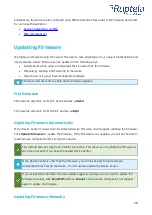
Page 41: ... extension for Eco4 RS T devices efwj4 Updating Firmware Automatically If the Device Center is newer than the detected device firmware it will suggest updating the firmware Click Update firmware to update the firmware If the firmware is not updated you will not be able to load and save configuration files from to the device This method does not require an internet connection This allows you to upd...

Page 42: ... firmware with the fwp pack click Connect and Send FW in the main configurator menu Locate your firmware fwp pack and click Open The advanced configurator will upload the required device firmware file s and the update process will start Updating Firmware Over the air The exact process of how to update firmware over the air depends on your fleet management software The following conditions must be ...

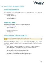
Page 43: ...he installation is carried out only by qualified personnel Before starting the installation decide where you will install the device The installation location depends on the vehicle and selected installation method Follow these recommendations to ensure that the device works properly Install the device in a service access area under the dashboard behind the fuse box etc Fix the device firmly to th...

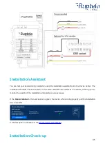
Page 44: ...SS antenna behind the dashboard as close to the windshield as possible and further away from the doors It must be uncovered and facing up as shown in the picture below Correct Incorrect Incorrect antenna placement may result in reduced tracking accuracy Wiring Diagram Regular Housing Power input 6 31 5 V DC ...

Page 45: ... or solder wire connectors insulating tape and similar materials can be used Wiring Diagram IP67 Housing Power input 6 31 5 V DC It is mandatory to use an external automotive 1 A fuse We recommend using specialized insulation methods that ensure reliable long term performance under harsh field conditions Heat shrink connectors crimp or solder wire connectors insulating tape and similar materials c...

Page 46: ...checks the status of the main modules and interfaces in real time allowing you to monitor the quality of the installation and quickly solve any issues If the Overall status in the overview bar is green the device is functioning properly and the installation was successful A full description is available in the Device Center User Manual Installation Check up ...

Page 47: ... to mobile networks and the internet Command syntax password gsminfo Response example ST 2019 06 20 23 26 33 OP 22210 lvl 15 LAC 20030 CID 28289 GSM M I 126 R 125 SP 0 GPRS 0 O 64 C 0 E 248 LK O 575 E 1 TMO 126 RS 04 P 0 The relevant parameters and their values are described in the table below lvl The mobile signal level If lvl is lower than 10 the signal is weak and it is likely that there is no ...

Page 48: ...9 06 20 07 01 lat 46 1443183 long 11 881766 alt 217 5 sat 8 dir 198 10 hdop 100 state 3 The relevant parameters and their values are described in the table below Datetime The current date and time in GMT sat The number of visible satellites At least 4 satellites must be visible to get an accurate GNSS signal hdop The current HDOP signal accuracy level If the HDOP level is above 3 5 the GNSS signal...

Page 49: ...48 Response example Resetting device ...

Page 50: ...ia the web or using an app Use the same server domain typically track2 ruptela com for both web and app Your login credentials are sent to you by e mail If you have not received them contact your sales manager Accessing TrustTrack via Web To access TrustTrack via the web enter your server domain into the browser Enter your credentials and click Sign In Accessing TrustTrack via App Download the Tru...

Page 51: ...hone settings The app will ask you for the server domain upon the next launch Verifying Vehicle Status After logging in click the Fleet status button in the left menu panel Find your vehicle in the Fleet Status panel and click on it Check the State duration and Last signal sync in the additional panel If they have recently been updated data transfer is successful and the device is properly install...

Page 52: ...51 ...

Reviews: