


10 REVT-05ERV
2.
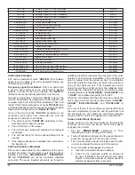
A manual gas shut-off valve (furnished by installer)
must be installed immediately adjacent to the point
where the gas supply enters the cabinet. Codes may
require that both a manual main shut-off valve and a
union be installed and that the union must be of the
ground joint type.
See Figure 6.
3. Always use clean, scale-free pipe and malleable iron
fittings, and remove all cutting and threading debris
prior to connecting pipes.
4. Firmly support the gas piping so that it cannot be
dislodged from its installed position.
A. DUCT SIZING and CONNECTION
NOTE: Recommended duct sizes shown in Figure 4
result in duct velocities over the published cfm range
for each model of approximately 300 feet per second
minimum for the EVT-09 (600 cfm) to approximately
1200 feet per second maximum for the EVT-12 (12,000
cfm).
1. No holes should be drilled into the base of the Unit
for the installation of ductwork, all ductwork should be
attached to a roof curb that is either factory supplied
or built to manufacturer’s specifications.
2. Installation of ducts should be done in accordance
with SMACNA and SMCA guidelines.
3.
Units with horizontal supply and return ductwork
should have the bottom supply and return openings
closed off and sealed.
IMPORTANT: All downflow units with any Gas or
Electric post heat options must have a sheet metal
L or T shaped supply duct that makes a transition
from vertical to horizontal directly below the
supply opening. No outlets or registers should be
placed directly below the supply opening.
B. GAS PIPING (OPTION)
NOTE: Before connecting gas piping, check with gas
provider or local authorities having jurisdiction
for local code requirements. When installing gas
supply piping, length of run from gas meter must
be considered in determining pipe size for 0.5
i.w.c. (0.12 kPa) maximum pressure drop. Do not
use supply pipe smaller than unit gas connection.
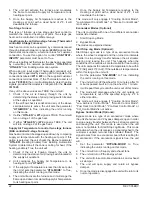
GROUND JOINT UNION
DRIP LEG
MANUAL SHUT-OFF VALVE
GAS PIPING SUPPORT
TO GAS SUPPLY (REFER TO LOCAL CODES)
FIGURE 6 - GAS SUPPLY PIPING
For natural gas units, operating pressure at the
unit gas connection must be a minimum of 4.7
i.w.c. (1.17 kPa) and a maximum of 10.5 i.w.c. (2.60
kPa).
Connect Gas Piping
CAUTION
Some soaps used for leak detection are corrosive
to certain metals. Carefully rinse piping thoroughly
after leak test has been completed. Do not use
matches, candles, flame or other sources of ignition
to check for gas leaks.
1. All gas piping shall conform with local codes and
ordinances or, in the absence of local codes, to the
National Fuel Gas Code or ANSI Z223.1. In Canada,
installation must be in accordance with CAN/
CGA-B149.1 for Natural Gas.
2.
A manual gas shut-off valve (furnished by installer)
must be installed immediately adjacent to the point
where the gas supply enters the cabinet. Codes may
require that both a manual main shut-off valve and a
union be installed and that the union must be of the
ground joint type.
See Figure 6.
3. Always use clean, scale-free pipe and malleable iron
fittings, and remove all cutting and threading debris
prior to connecting pipes.
4. Firmly support the gas piping so that it cannot be
WARNING
Danger of explosion. Can cause injury
or product or property damage. Do not
use matches, candles, flame or other
sources of ignition to check for leaks.
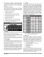
MAIN CONDENSATE
DRAIN (SEE FIGURE 12)
ROOF MOUNTING FRAME
ROOF STRUCTURE
DRAIN P-TRAP
FIGURE 7 - CONDENSATE ROOF DRAIN
NOTE: Use a PVC T-fitting with a cap to provide
washout access for the P-trap.
Summary of Contents for ENERVENT+ EVT-09 Series
Page 30: ...30 REVT 05ERV UNIT WIRING DIAGRAM ...
Page 31: ...REVT 05ERV 31 UNIT WIRING DIAGRAM CONTINUED ...
Page 47: ...REVT 05ERV 47 UNIT WIRING DIAGRAM XVIII WIRING DIAGRAMS ...
Page 48: ...48 REVT 05ERV UNIT WIRING DIAGRAM CONTINUED ...
Page 50: ...50 REVT 05ERV Optional Heat Cool Inputs Optional Pre Post Heat ...
Page 57: ...REVT 05ERV 57 DIAGRAM 15 5 1 MODULATION GAS POST HEAT DIAGRAM 14 2 STAGE GAS POST HEAT ...


