background image

REVT-05ERV 17

maintained entering the ERC by cycling a 2-stage electric 

heat unit located just after the fresh air hood.  The heater 

is  controlled  by  a  field  adjustable  temperature  sensor 

located at the inlet of the wheel.  If the temperature falls 

below the setpoint the first stage will turn on.  If that does 

not satisfy the load, the second stage turns on.  
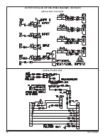
See Pre-

Heat wiring diagram for circuit logic.


H.  CO

2

 SENSOR

Helps control indoor air quality based on CO

2

 levels in 

the occupied space. High CO

2

 levels can either trigger 

a response from the ERV unit by turning on the blowers 

to bring in fresh air or by modulating the blowers if a 

VFD option has been selected. 

See Basic Unit wiring 

diagram for circuit information.
I.  ROTATION SENSOR

The circuit indicates the absence of pulses, within a 

specified  time  range,  provided  by  a  magnetic  sensor 

detecting a magnet mounted on wheel surface.  After the 

initial time delay of approximately 5 seconds from circuit 

power up, if the sensor fails to provide a signal pulse 

(no wheel rotation) within approximately 5 additional 

seconds, the alarm relay will activate the latch (until circuit 

powers down) providing a 5 amp contact closure output.  

This would indicate no wheel rotation and/or magnet in 

the system has stopped at the magnetic sensor pickup 

point.  If the pulse (wheel rotation) is detected within the 

approximately 5 second time period, the alarm relay will 

remain open.  No field timing adjustment of any type will 

be required. 

J.  SMOKE DETECTORS

Duct mounted smoke detectors can be installed in both 

return and/or supply air streams.  Signals from the smoke 

detectors can be set to start-up or shut-down the ERV unit 

if smoke is detected.  

See Basic Unit wiring diagram for 

circuit information.
K.  LOW AMBIENT KIT

Limits HVAC system operation when outdoor temperature 

is below 10°F.

L.  SENSIBLE-ONLY ERC

An Energy Transfer Wheel without the latent energy 

transfer capability of the standard Enthalpy Wheel is 

available for dry-climate application (RH less than 30%).  

This wheel does not have the Silica Gel coating applied.

M.  MERV 11 and 13 AIR FILTERS

All units are shipped with MERV 8 supply and exhaust 

air filters. MERV 11 or 13 filters are available as factory 

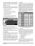
TABLE 5 - EXHAUST AIR LEAVING TEMPERATURE AND 

ENERGY RECOVERY WHEEL EFFECTIVENESS

EXHAUST AIR TEMPERATURE AND ERW EFFECTIVENESS

ERW  EFF

70

o

F AND 20% RH 

INDOORS

70

o

F AND 30% RH 

INDOORS

70

o

F AND 40% RH 

INDOORS

DESIGN 

TEMP

EAT

DESIGN 

TEMP

EAT

DESIGN 

TEMP

EAT

%

F

o

F

o

F

o

F

o

F

o

F

o

0.80

-13

4.0

-3

12.0

4

17.3

0.70

-15

11.0

-4.5

18.0

3

23.1

0.60

-19

17.0

-8

24.0

1

28.6

0.50

-26

22.0

-13

28.5

-3

33.5

0.45

-31

25.0

-17

31.0

-5

36.2

0.40

-40

26.0

-24

32.5

-10

38.0

installed  options.  MERV  8  filters  are  30-35%  efficient.  

MERV  11  provides  60-65%  efficiency  at  roughly  the 

same resistance level. The MERV 13 filter achieves the 

minimum  efficiency  requirements  (80-85%)  of  LEED 

Green Building design.  All are 2 inch thick, V-pleat design, 

supported with expanded metal with Minimum Efficiency 

Reporting Value determined per ASHRAE 52.2.

N.  ELECTRONIC TEMPERATURE CONTROL 

SYSTEM

Works in conjunction with optional heating and cooling 

coils to temper the supply air back to ambient conditions.  

Tempering the air entering the occupied pace allows 

Enervent to bring in 100% outside air without putting an 

additional load on the rooftop unit.  The ETCS can be 

entreated with a building automation system.

O.  FREE AIR APPLICATION

Operation of the Energy Recovery Wheel can be altered, 

sometimes referred to as Start, Stop, Jog, to take 

advantage  of  economizer  operation,  which  amounts  to 

free cooling.  This is accomplished by:

De-energizing  The  ERC  -  Accomplished  with  a  signal 

from a Primary Temperature Sensor mounted in the air 

intake  compartment.    This  sensor  will  de-energize  the 

energy wheel when the outdoor air temperature falls 

below the set point; which is factory set at 65°F, but is 

field  adjustable.    An  Override  temperature  sensor  is 

also furnished in the outdoor air intake compartment to 

deactivate the economizer mode.  This Override sensor, 

also field adjustable, is factory set at 50°F; i.e., something 

less that the Primary sensor.  The two sensors together 

create a deadband where the ERC will not operate and 

free cooling can enter the building unconditioned.

P.  GFCI SERVICE OUTLET

A 120 VAC GFCI service outlet is shipped loose for field 

installation.  Requires separate power source so power 

is  available  when  unit  main  disconnect  is  turned  off  for 

servicing.

Q.  EME INTAKE LOUVERS

A fresh air hood consisting of a built-in, louvered, moisture 

eliminator requiring no maintenance during the life of the 

unit.  This contrasts with the standard hood, which contains 

an aluminum mesh filter(s) requiring routine maintenance.  

The EME intake surface is parallel to front of the unit and 

extends outward approximately four inches.

R.  VFD BLOWER CONTROL

Variable Frequency Drives (VFD) control the blower 

speed. One VFD is provided for each blower (supply and 

return), as well as the ERC if Modulating frost Control 

is selected.. The VFDs provided are Johnson Controls 

DC* line of drives manufactured by Eaton. Refer to the 

Drive’s manual included with the ERV for further technical 

specifications and information.

Refer to the VFD operation manual Chapter 5 for 

information on parameters. Most manufactures setpoints 

are retained except for :

P1 - Max Frequency - set to 60Hz

P2 - Min Frequency - set to 21.5 Hz

P7 - Operating Voltage - off motor nameplate

P8 - Motor AMPS - off motor nameplate

Summary of Contents for ENERVENT+ EVT-09 Series

Page 1: ...NECTIONS OPTION 11 E DIRECT EXPANSION COIL CONNECTIONS OPTION 11 XI ELECTRICAL CONNECTIONS A BASE UNIT POWER SUPPLY 12 B POST HEAT POWER SUPPLY OPTION 12 C PRE HEAT POWER SUPPLY OPTION 13 D CONTROL WIRING 13 XII BLOWER OPERATION A 3 PH VOLTAGE PHASING 14 B SPEED SETTING 14 C PULLEY ALIGNMENT 14 D BELT ADJUSTMENT 14 E FIELD FURNISHED BLOWER DRIVES 15 XIII OPTIONS FACTORY INSTALLED A ELECTRIC PRE HE...

Page 2: ...Exhaust Air Indoor Horizontial H B Fresh Exhaust Air Indoor Downflow Y Drain Pans Revision Level G Galvanized First Generation X S Stainless steel Second Generation A Control Package Intake Blower Speed A Standard Controls W Contactors Low Speed L B Standard Controls W Contactors Display Meduim Speed M C BAS Controls W VFDs High Speed H D BAS Controls W VFDs Display Exhaust Blower Speed C CO2 Sens...

Page 3: ...d the unit can be controlled via thermostat SUPPLEMENTAL POST HEAT FIGURE 1 TYPICAL CABINET FEATURES AND OPTIONS II GENERAL III PARTS ARRANGEMENT Figure 1 shows the parts arrangement for the typical cabinet including major standard features and factory installed options that are offered and therefore may be included in the unit being installed The units shown are typical of the entire series with ...

Page 4: ...llow independent balancing of supply and exhaust airflow 7 VIBRATION ISOLATORS Both the supply and the exhaust blowers are mounted on neoprene vibration isolators providing additional acoustical performance 8 BLOWER MOTORS and DRIVES NEMA Premium Efficient motors that exceed requirements of Energy Policy Act of 1992 Base mount with easy adjustment of belt tension Mounting permits slide out of moto...

Page 5: ... Post Heat An ETL Certified Component with controls wired at the factory Single point power for the heating elements to be field provided Staging ranges from 1 to 4 depending on the unit size and heater option selected 17 TEMPERING COILS Copper tube and aluminum fin construction rated in accordance to ARI Standard 410 Tubing and return bends are seamless copper conforming toASTM B75 andASTM B251 f...

Page 6: ...eat energy meaning sensible heat energy plus latent heat energy Sensible and latent heat are the two components of total heat Sensible heat is the energy contained in dry air and can be recovered by simply effecting a temperature change in a given VOLUME of air While latent heat is the energy contained in the water vapor within moist air During the summer cooling season the latent heat can only be...

Page 7: ...ow ignition input rate temperature rise and venting must be verified according to these installation instructions VIII UNIT PLACEMENT and SUPPORT A POSITIONING MIN CLEARANCES General Unit Requirements Do not position the unit with the outdoor air intake into the prevailing wind and keep the intake away from any other exhaust fans Likewise position the exhaust discharge opening away from the outdoo...

Page 8: ...aking in roof may occur if unit base is punctured or liquidated damages whatsoever as a result of purchasing another vendors roof curbs or other accessories that have not been first approved by RRS Therefore any failures of said equipment due to the non use of RRS roof curb accessories will render any warranties provided with said equipment to be null and void Roof Mounting with Ruskin 022E1 RMF 1...

Page 9: ...ON UNIT X UNIT INSTALLATION A DUCT SIZING and CONNECTION NOTE Recommended duct sizes shown in Figure 4 result in duct velocities over the published cfm range for each model of approximately 300 feet per second minimum for the EVT 09 600 cfm to approximately 1200 feet per second maximum for the EVT 12 12 000 cfm 1 No holes should be drilled into the base of the Unit for the installation of ductwork...

Page 10: ... jurisdiction for local code requirements When installing gas supply piping length of run from gas meter must be considered in determining pipe size for 0 5 i w c 0 12 kPa maximum pressure drop Do not use supply pipe smaller than unit gas connection GROUND JOINT UNION DRIP LEG MANUAL SHUT OFF VALVE GAS PIPING SUPPORT TO GAS SUPPLY REFER TO LOCAL CODES FIGURE 6 GAS SUPPLY PIPING For natural gas uni...

Page 11: ...r to operating this unit for the first time it is important to leak test all gas piping and fix any leaks before turning on the unit 2 Isolate the gas valve from the gas supply system by closing its individual manual shut off valve or by disconnecting it from the gas supply piping system during any pressure testing equal to or more than 0 5 psig 3 48 kPa 3 After all connections have been made and ...

Page 12: ...pplies Do not apply power or close disconnect switch until installation is complete Refer closely to start up directions and to unit wiring diagram on inside of control box access door or see Pages 47 57 Electric and Gas Post Heat unit wiring diagrams respectively Wiring diagrams for each pre heat and post heat electric and gas option can be found in SECTION XVIII WIRING DIAGRAMS 1 230 460 575 vol...

Page 13: ...NTROL WIRING Route low voltage control wire from thermostat or energy management through small bushing in the upper right corner of the Base Unit Control Box as shown in Figure 14 PRE HEAT ELECTRICAL SERVICE ENTRANCE EXHAUST AIR HOOD OUTDOOR AIR HOOD GAS POST HEAT OPTION PRE HEAT ELECTRICAL SERVICE ENTRANCE FIGURE 14 THERMOSTAT CONTROL CONNECTIONS IMPORTANT Unless field thermostat wires are rated ...

Page 14: ...ing the motor pulley Loosen the Allen screw and turn adjustable pulley clockwise to increase RPM and counterclockwise to decrease RPM Repeat this process for the return exhaust side to determine the RPM and BHP requirements for that blower C PULLEY ALIGNMENT All Pulleys are laser aligned in the factory during production movement of the pulleys is possible however if the set screws weren t properly...

Page 15: ...e does not satisfy the set point the second stage will also turn on B TEMPERING COILS Factory installed cooling and or heating coils are mounted downstream of the Energy Recovery Cassette ERC on the supply air side of the unit All connections are located external to the unit Water coil connections are wrought copper MPT and refrigerant coil connections suction and liquid are SWT All coils are copp...

Page 16: ...0 60 30 10 000 7 500 5 000 2 500 Exhaust Air Mounts between the exhaust blower and the return air exhaust hood Operates in conjunction with Motorized Intake Air Damper Powered by B31 damper motor F DIRTY FILTER SENSOR Measures pressure drop across Intake and Exhaust Filters and sends a signal to field wired alarm when filters require maintenance G FROST CONTROL Extremely cold outdoor air temperatu...

Page 17: ...0 5 36 2 0 40 40 26 0 24 32 5 10 38 0 installed options MERV 8 filters are 30 35 efficient MERV 11 provides 60 65 efficiency at roughly the same resistance level The MERV 13 filter achieves the minimum efficiency requirements 80 85 of LEED Green Building design All are 2 inch thick V pleat design supported with expanded metal with Minimum Efficiency Reporting Value determined per ASHRAE 52 2 N ELE...

Page 18: ...Return Air Temperature Resistance AI 25410 IN6 EA TEMP REST Exhaust Air Temperature Resistance AI 25404 IN7 WHL FAIL SIG Wheel Failure Signal BI 10005 IN8 OCC STS Occupancy Status BI 17564 Outputs OUT1 SA FAN CMD Supply Air Fan Command BO 10017 OUT2 EA FAN CMD Exhaust Air Fan Command BO 17525 OUT3 WHL CMD Wheel Command BO 10023 OUT4 MOH CMD Outside Air Hood Command BO 15224 OUT5 MEH CMD Exhaust Ai...

Page 19: ...ass Mode Flag BV 22435 EMG STANDALONE HTG Emergency Standalone Heating Mode Flag BV 32050 SSJ MIN TEMP Start Stop Jog Min Temperature AV 10186 SSJ MAX TEMP Start Stop Jog Max Temperature AV 10187 SSJ ONTIME Start Stop Jog Wheel On Time AV 10184 SSJ OFFTIME Start Stop Jog Wheel Off Time AV 10183 HTG MINOFF Gas Heat Minimum Off Time For 2 stage Gas Heating AV 32052 HTG MINON Gas Heat Minimum On Time...

Page 20: ...unit will set the START UP parameter to True indicating unit is ready to operate 2 The unit will turn on the wheel 3 The unit will open motorized outside air and exhaust air damper 4 The unit will check for the motorized dampers to be opened 5 If the damper statuses are satisfied then unit will turn the blowers on Set Point Validation Standard This mode is responsible for the validations of the us...

Page 21: ...Ambient Control Mode or Smoke Control Mode is not active Cooling Control Mode Optional Cooling control mode is responsible for the control of optional cooling coils shipped with the unit The cooling coils are controlled in 2 different ways Cooling control is operated by commands issued through a Bacnet network or physical 24VAC signals from thermostat connected to a terminal block for customer con...

Page 22: ...upply Air Temperature is less than its set point then Unit sets the parameter HTG MODE to True indicating the unit is running on this mode 4 The unit will activate the furnace and it will stage the flame up and down to maintain SupplyAir Temperature to its heating set point 5 Once the Supply Air Temperature reaches to the Heating set point with a dead band of 2 F it will deactivate the furnace Thi...

Page 23: ...y interchanging any two of the three field installed electrical leads C FAN RPM The adjustable sheave on both the supply and the exhaust blowers are factory set to the mid range rpm for the selected drive kit Refer to Section XII Blower Operation for instructions on changing blower RPM and proper sheave alignment and belt tension Before powering the blower all access doors other than the unit Cont...

Page 24: ...ntrol move the thermostat switch to OFF and then return the thermostat switch to HEAT WARNING WARNING WARNING Danger of explosion Can cause injury or product or property damage If overheating occurs or if gas supply fails to shut off shut off the manual gas valve to the appliance before shutting off electrical supply Danger of explosion Can cause injury or death Do not attempt to light manually Un...

Page 25: ...CAUTION Disconnect heating demand as soon as an accurate reading has been obtained CAUTION For safety connect a shut off valve between the manometer and the gas tap to permit shut off of gas pressure to the manometer High Altitude Derate Natural gas units may be installed at altitudes up to 2000 feet 610m above sea level without any modification At altitudes above 2000 feet 610m units must be dera...

Page 26: ...INDUCER HEAT EXCHANGER TUBES ALUMINIZED STD EVT 09THRU 88 STAINLESS STEEL STD EVT 10 12 OPTION EVT 09 THRU 88 COMBUSTION AIR PROVING SWITCH PRESSURE TAP 2 STAGE GAS VALVE FLUE EXHAUST VENT BURNER RACK ASSEMBLY IGNITION CONTROL BOARD STAINLESS STEEL HEAT EXCHANGER TUBES GAS SUPPLY LINE SEE FIGURE 9 2 STAGE GAS VALVE PRESSURE TAP MODULATION GAS VALVE GAS HEAT CONTROL COVER IGNITION CONTROL BOARD GAS...

Page 27: ...ier s instructions If you do not smell gas go to the next step 7 Turn the gas valve control knob counterclockwise to the ON position 8 Close the heat section access door 9 Turn gas supply to ON position 10 Turn electrical power on 11 Set thermostat switch to HEAT and turn to the highest setting 12 LED light at the ignition will light up 13 Induced draft blower will run for a 30 second pre purge pe...

Page 28: ...tion attempt after lockout may be re established manually by moving the thermostat switch to OFF and then return to HEAT position 9 When the warm up period expires modulation of the system is handed over to the Building Management System 10 If the building controller is providing an analog signal between 2 0 and 5 3 vdc to the SC30 Control the system will continue to operate at low fire and low sp...

Page 29: ...29 FACTORY INSTALLED OPTIONS WIRING DIAGRAMS Optional Pivot Optional Rotation Sensor Optional MOH MEH Optional VFD Optional Bypass Optional CO2 Sensor Optional Smoke Detector Optional DX Coil Optional Dirty Filter ...

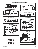
Page 30: ...30 REVT 05ERV UNIT WIRING DIAGRAM ...

Page 31: ...REVT 05ERV 31 UNIT WIRING DIAGRAM CONTINUED ...

Page 32: ...32 REVT 05ERV FACTORY INSTALLED OPTIONS WIRING DIAGRAMS CONTINUED Optional Heat Cool Inputs Optional Pre Post Heat ...

Page 33: ...mesh filter s located in the standard Fresh Air Hood See Figure 26 must be cleaned on a regular basis for best efficiency not applicable for units with EME The frequency depends on cleanliness of the incoming air B SUPPLY AND RETURN AIR FILTERS Supply Air Filters Located upstream of the Enthalpy Wheel as shown in Figure 27 Should be checked regularly and cleaned or replaced Again the frequency dep...

Page 34: ...ead instructions for mixing antifreeze solution used Some products will have a higher freezing point in their natural state than when mixed with water D ENERGY RECOVERY CASSETTE ERC Cleaning Wheel Over time build up of material on energy transfer surfaces reduces latent energy water vapor transfer and reduces air flow Therefore periodic cleaning is required to maintain building moisture control an...

Page 35: ...ason examine the burners for any deposits or blockage which may have occurred If Necessary Clean burners as follows 1 Turn off both electrical power and gas supply to unit 2 Open burner compartment access door 3 Remove two screws securing burners to burner support and lift the burners from the orifices See Figure 32 Clean as necessary 4 Replace burners and screws securing burner 5 Close access doo...

Page 36: ...signal through the flame the Spark Igniter is de energized immediately During operation flame is sensed by current passed along the ground electrode located on the Spark Igniter through the flame and into the Sensor electrode The Ignition Control allows the Gas Valve to remain open as long as a flame signal current passed through the flame is sensed Gas Valve 2 Stage and 5 1 Modulation A two stage...

Page 37: ... California has determined that this product may contain or produce a chemical or chemicals in very low doses which may cause serious illness or death It may also cause cancer birth defects or reproductive harm FIGURE 36 SLIDE OUT BLOWER ASSEMBLY BLOWER ACCESS DOOR REMOVE SCREWS TO SLIDE BLOWER ASSEMBLY OUT OF UNIT FLUE VENT COVER DISENGAGE HANDLE BEFORE ATTEMPTING TO REMOVE STATIONARY PANEL REMOV...

Page 38: ...Based on Drive Rating P032 Motor Nameplate Hertz 60 Hz Default P033 Motor Overload Current Based on Motor FLA Rating P034 Minimum Frequency 0 0 Hz Default P035 Maximum Frequency 60 0 Hz Default P036 Start Source 2 Wire P037 Stop Mode 0 Coast Default P038 Speed Reference 2 0 10 Volt Input 3 4 20 ma Input P039 Acceleration Time 10 sec Default P040 Deceleration Time 10 sec Default P041 Reset to Defau...

Page 39: ...ust ESP in wg Min 0 0 0 0 0 Max 1 1 1 1 1 Weight lbs 1510 1670 2610 2780 3080 TABLE 14 UNIT SPECIFICATIONS EVT Unit EVT 62 EVT 74 EVT 88 EVT 10 EVT 12 CFM Range Min Max 3 400 6 200 5 400 7 400 6 400 8 800 7 600 10 000 8 000 12 000 ERC Model 5262 5874 6488 68100 74122 Supply Blower Model A15 x 11A A18 x 13A A18 x 13A A20 x 9H 2 A20 x 9H 2 Shaft Dia in 1 188 1 188 1 188 1 438 1 438 Max RPM 1714 1478...

Page 40: ...0 04 0 12 0 04 0 05 3800 0 17 0 08 0 15 0 16 0 18 0 08 0 15 0 27 0 32 0 07 0 03 0 06 0 02 0 05 0 15 0 05 0 06 4200 0 21 0 10 0 18 0 19 0 21 0 09 0 18 0 32 0 37 0 09 0 03 0 07 0 03 0 06 0 20 0 06 0 07 4600 0 25 0 12 0 21 0 22 0 24 0 11 0 21 0 37 0 43 0 10 0 04 0 08 0 04 0 07 0 24 0 07 0 08 EVT 62 3400 0 13 0 07 0 13 0 14 0 15 0 10 0 15 0 30 0 28 0 06 0 02 0 05 0 02 0 04 0 11 0 04 0 03 4100 0 19 0 1...

Page 41: ...1516 2 57 1614 2 87 1709 3 17 2800 3415 1032 1 62 1145 1 91 1255 2 20 1361 2 50 1461 2 81 1555 3 12 1648 3 44 1738 3 76 EVT 28 EXHAUST AIR PERFORMANCE RATINGS AIR VOLUME CFM OUTLET VELOCITY FPM TOTAL STATIC PRESSURE In w g 0 00 0 50 1 00 1 50 2 00 2 50 3 00 3 50 RPM BHP RPM BHP RPM BHP RPM BHP RPM BHP RPM BHP RPM BHP RPM BHP 1600 1416 645 0 29 852 0 46 1024 0 64 na na na na na na na na na na 1900 ...

Page 42: ...200 2719 687 2 67 784 3 25 873 3 85 957 4 47 1036 5 10 1111 5 74 1182 6 41 1250 7 09 EVT 74 SUPPLY AIR PERFORMANCE RATINGS AIR VOLUME CFM OUTLET VELOCITY FPM TOTAL STATIC PRESSURE In w g 0 00 0 50 1 00 1 50 2 00 2 50 3 00 3 50 RPM BHP RPM BHP RPM BHP RPM BHP RPM BHP RPM BHP RPM BHP RPM BHP 5400 2368 575 1 66 687 2 17 789 2 70 881 3 24 968 3 80 1050 4 38 1126 4 98 1199 5 59 5900 2588 608 2 07 714 2...

Page 43: ...M BHP 8000 2360 523 2 56 610 3 27 692 4 03 770 4 85 845 5 72 916 6 62 984 7 55 1049 8 51 9000 2655 569 3 46 649 4 25 707 4 89 795 5 96 865 6 89 932 7 85 996 8 85 1058 9 88 10000 2950 615 4 56 688 5 41 757 6 31 824 7 25 888 8 24 951 9 26 1011 10 33 1070 11 43 11000 3245 660 5 85 728 6 78 793 7 75 854 8 75 914 9 80 973 10 89 1030 12 01 1086 13 17 12000 3540 703 7 32 768 8 36 828 9 39 886 10 46 942 1...

Page 44: ...0 430 151 MED 843 1167 1VP40x7 8 700 000 053 AK56x1 700 000 052 AX50 410 430 152 3 2 24 3 45 2 57 1 125 HIGH 1333 1750 1VP44x1 1 8 700 000 100 BK45x1 700 000 114 BX50 410 430 159 MED 1111 1395 1VP60x1 1 8 700 000 059 BK77x1 700 000 092 BX58 410 430 161 5 3 73 5 75 4 29 HIGH 1422 1750 1VP65x1 1 8 700 000 102 BK67x1 700 000 115 BX57 410 430 160 EXHAUST A12 12A 1 188 1 5 1 12 1 73 1 29 0 875 HIGH 795...

Page 45: ...6 700 000 101 BX45 410 430 128 LOW 789 932 2VP71x1 3 8 700 000 105 2AK124x1 7 16 700 000 125 NA NA AX52 410 430 116 10 11 50 8 58 HIGH 1046 1263 2VP71x1 3 8 700 000 105 2BK100x1 7 16 700 000 127 BX47 410 430 130 EVT 10 SUPPLY TWIN A20 9H 1 438 5 3 45 2 57 1 125 HIGH 648 813 1VP60x1 1 8 700 000 059 1B5V124 700 000 134 B 1 7 16 700 000 101 BX88 410 430 165 MED 558 687 1VP65x1 1 8 700 000 102 1B5V160...

Page 46: ...0 1 740 1 610 1 500 1 410 EVT 46 2 200 000 162 000 7 500 6 000 5 000 4 290 3 750 3 340 3 000 2 730 2 500 2 310 2 150 2 000 1 880 EVT 62 2 250 000 202 500 9 380 7 500 6 250 5 360 4 690 4 170 3 750 3 410 3 130 2 890 2 680 2 500 2 350 EVT 74 2 300 000 243 000 11 250 9 000 7 500 6 430 5 625 5 000 4 500 4 100 3 750 3 460 3 210 3 000 2 800 EVT 88 2 350 000 283 500 13 130 10 500 8 750 7 500 6 570 5 840 5...

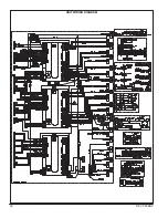
Page 47: ...REVT 05ERV 47 UNIT WIRING DIAGRAM XVIII WIRING DIAGRAMS ...

Page 48: ...48 REVT 05ERV UNIT WIRING DIAGRAM CONTINUED ...

Page 49: ... XIX FACTORY INSTALLED OPTIONS WIRING DIAGRAMS Optional Pivot Optional Rotation Sensor Optional MOH MEH Optional Bypass Optional CO2 Sensor Optional Smoke Detector Optional DX Coil Optional Dirty Filter Optional VFD ...

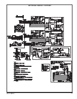
Page 50: ...50 REVT 05ERV Optional Heat Cool Inputs Optional Pre Post Heat ...

Page 51: ...ating Element M Manual Limit reset Thermal cut out T Transformer Control W Heating Demand Thermostat Legend A Automatic Limit reset Thermal cut out C Contactor Control CM Contactor Backup DPS Differential Pressure Switch F Fuse G Ground H Heating Element M Manual Limit reset Thermal cut out T Transformer Control W Heating Demand Thermostat EVT 09 thru EVT 19 Single Stage 240 480 575V EVT 74 thru E...

Page 52: ...l W Heating Demand Thermostat Legend A Automatic Limit reset Thermal cut out C Contactor Control CM Contactor Backup DPS Differential Pressure Switch F Fuse G Ground H Heating Element M Manual Limit reset Thermal cut out T Transformer Control W Heating Demand Thermostat EVT 19 Two Stage 240 480 575V EVT 36 Two Stage 480 575V EVT 46 thru EVT 62 Two Stage 240 480 575V DIAGRAM 5 ELECTRIC POST HEAT DI...

Page 53: ...Heating Demand Thermostat Legend A Automatic Limit reset Thermal cut out C Contactor Control CM Contactor Backup DPS Differential Pressure Switch F Fuse G Ground H Heating Element M Manual Limit reset Thermal cut out T Transformer Control W Heating Demand Thermostat EVT 36 thru EVT 62 Two Stage 240V EVT 74 thru EVT 12 Two Stage 480 575V EVT 74 thru EVT 12 Two Stage 240V DIAGRAM 7 ELECTRIC POST HEA...

Page 54: ... Delay W Heating Demand Thermostat Legend A Automatic Limit reset Thermal cut out C Contactor Control CM Contactor Backup DPS Differential Pressure Switch F Fuse G Ground H Heating Element M Manual Limit reset Thermal cut out T Transformer Control TD Time Delay W Heating Demand Thermostat EVT 62 Three Stage 240V EVT 88 thru EVT 12 Three Stage 480 575V EVT 62 Three Stage 480V DIAGRAM 9 ELECTRIC POS...

Page 55: ...ntrol TD Time Delay W Heating Demand Thermostat Legend A Automatic Limit reset Thermal cut out C Contactor Control CM Contactor Backup DPS Differential Pressure Switch F Fuse G Ground H Heating Element M Manual Limit reset Thermal cut out T Transformer Control TD Time Delay W Heating Demand Thermostat EVT 62 Three Stage 575V EVT 88 thru EVT 12 Three Stage 240V DIAGRAM 11 ELECTRIC POST HEAT DIAGRAM...

Page 56: ... T Transformer Control TD Time Delay W Heating Demand Thermostat Legend A Automatic Limit reset Thermal cut out C Contactor Control CM Contactor Backup DPS Differential Pressure Switch F Fuse G Ground H Heating Element M Manual Limit reset Thermal cut out T Transformer Control TD Time Delay W Heating Demand Thermostat EVT 12 Four Stage 480 575V DIAGRAM 13 ELECTRIC POST HEAT DIAGRAM 12 ELECTRIC POS...

Page 57: ...REVT 05ERV 57 DIAGRAM 15 5 1 MODULATION GAS POST HEAT DIAGRAM 14 2 STAGE GAS POST HEAT ...

Page 58: ...Contactor Backup DPS Differential Pressure Switch F Fuse G Ground H Heating Element M Manual Limit reset Thermal cut out PH Heating Demand Controller T Transformer Control EVT 09 thru EVT 12 Single Stage 240 480 575V DIAGRAM 17 ELECTRIC PRE HEAT DIAGRAM 16 10 1 MODULATION GAS POST HEAT ...

Page 59: ...Control TD Time Delay Legend AA Automatic Limit reset Thermal cut out C Contactor Control CM Contactor Backup DPS Differential Pressure Switch F Fuse G Ground H Heating Element M Manual Limit reset Thermal cut out PH Heating Demand Controller T Transformer Control TD Time Delay EVT 09 thru EVT 62 Two Stage 240 480 575V EVT 74 thru EVT 12 Two Stage 480 575V EVT 74 thru EVT 12 Two Stage 240V DIAGRAM...

Page 60: ...ans are running backwards de energize power to the unit then swap two of the three incoming electrical lines to obtain proper phasing Re check Perform all start up procedures outlined in the installation manual shipped with the unit Fill in the Start Up Information as outlined on the opposite side of this sheet Provide owner with information packet Explain the thermostat and unit operation START U...

Reviews: