18 REVT-05ERV
EVT Communications
The unit communication baud rate is set at 38400. The
MAC Address and device instance is set to customer
specifications per job. Communication is established
by connecting to the terminal block labeled Bacnet. It is
connected using an MS/TP network.
EVT Parameters
The unit ships with different set of parameters. These set
are separated into 3 categories:
• Hardware Inputs/Outputs:
Hardware Inputs/Outputs are the devices such as
Sensors, Actuators, Relays etc. connected to the
XIV - EVT SEQUENCE OF OPERATION (JCI)
Inputs/Outputs of the controller to monitor and control
the unit’s behavior.
• Control Points:
Control points are intended to control the unit’s
behavior. Control points are meant to be overwritten
by the user according to the buildings requirement.
• Monitoring points:
Monitoring points are intended to monitor the unit’s
behavior. Monitoring points are read only points to
inspect the unit’s functionality.
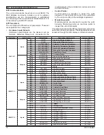
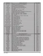
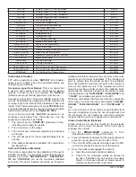
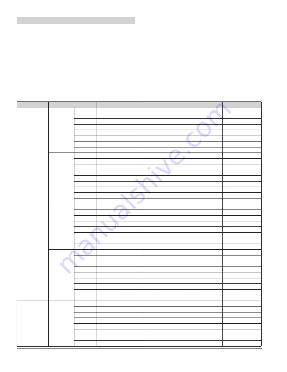
The tables below show the different parameter set and the
description for each parameter. These parameters can be
accessed through the HMI display or a Bacnet network.
Controller
Input/ Output
Object Name
Description (Hardware IO)
Instance Number
FAC 2611
Inputs
IN1
SA-DP
Supply Air Differential pressure
AI 10011
IN2
EA-DP
Exhaust Air Differential Pressure
AI 10047
IN3
OA-TEMP-REST
Outside Air Temperature Resistance
AI 25407
IN4
SA-TEMP-REST
Supply Air Temperature Resistance
AI 25413
IN5
RA-TEMP-REST
Return Air Temperature Resistance
AI 25410
IN6
EA-TEMP-REST
Exhaust Air Temperature Resistance
AI 25404
IN7
WHL-FAIL-SIG
Wheel Failure Signal
BI 10005
IN8
OCC-STS
Occupancy Status
BI 17564
Outputs
OUT1
SA-FAN-CMD
Supply Air Fan Command
BO 10017
OUT2
EA-FAN-CMD
Exhaust Air Fan Command
BO 17525
OUT3
WHL-CMD
Wheel Command
BO 10023
OUT4
MOH-CMD
Outside Air Hood Command
BO 15224
OUT5
MEH-CMD
Exhaust Air Hood Command
BO 17742
OUT6
Spare
OUT7
HTG-CMD
Heating Command
BO 21240
OUT8
SA-FAN-OUT
Supply Fan Output
AO 28730
OUT9
EA-FAN-OUT
Exhaust Fan Output
AO 28746
IOM4711-1
Inputs
IN1
BYP-STS
Bypass Damper Status
BI 24231
IN2
MOH-STS
Motorized Outside Air Damper Status
BI 17503
IN3
MEH-STS
Motorized Exhaust Air Damper Status
BI 17506
IN4
ECON-SIG
Economizer Signal
BI 22410
IN5
SMOKE-ALM
Smoke Alarm
BI 17573
IN6
AF-STS
Air Flow Status
BI 21644
IN7
OAFILT-STS
Outside Air Filter Status
BI 23783
IN8
RAFILT-STS
Return Air Filter Status
BI 23786
Outputs
OUT1
CLG1-CMD
Cooling 1 Command
BO 23797
OUT2
CLG2-CMD
Cooling 2 Command
BO 21249
OUT3
PREHEAT-CMD
Pre Heat Command
BO 21252
OUT4
BYP-CMD
Bypass Damper Command
BO 21258
OUT5
HTG1-CMD
Heating Stage 1 Command
BO 30120
OUT6
HTG2-CMD
Heating Stage 2 Command
BO 30123
OUT7
Spare
OUT8
HTG-OUT
Heating Output
AO 21255
OUT9
WHL-OUT
Wheel Modulating Signal Output
AO 10014
IOM4711-2
Inputs
IN1
RA-CO2
Return Air CO2
AI 10008
IN2
CLG1-SIG
Cooling 1 Signal (Y1)
BI 24108
IN3
CLG2-SIG
Cooling 2 Signal (Y2)
BI 24111
IN4
HTG1-SIG
Heating 1 Signal (W1)
BI 24114
IN5
HTG2-SIG
Heating 2 Signal (W2)
BI 24117
IN6
Spare
IN7
SA-FAN-STS
Supply Air Fan Status
BI 17496
IN8
EA-FAN-STS
Exhaust Air Fan Status
BI 17500
Summary of Contents for ENERVENT+ EVT-09 Series
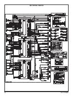
Page 30: ...30 REVT 05ERV UNIT WIRING DIAGRAM ...
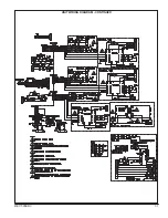
Page 31: ...REVT 05ERV 31 UNIT WIRING DIAGRAM CONTINUED ...
Page 47: ...REVT 05ERV 47 UNIT WIRING DIAGRAM XVIII WIRING DIAGRAMS ...
Page 48: ...48 REVT 05ERV UNIT WIRING DIAGRAM CONTINUED ...
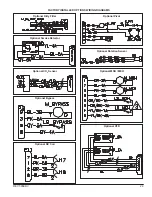
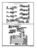
Page 50: ...50 REVT 05ERV Optional Heat Cool Inputs Optional Pre Post Heat ...
Page 57: ...REVT 05ERV 57 DIAGRAM 15 5 1 MODULATION GAS POST HEAT DIAGRAM 14 2 STAGE GAS POST HEAT ...


