


REVT-05ERV 25
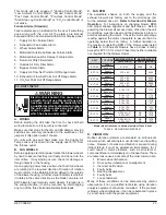
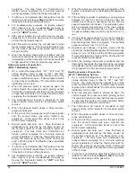
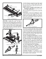
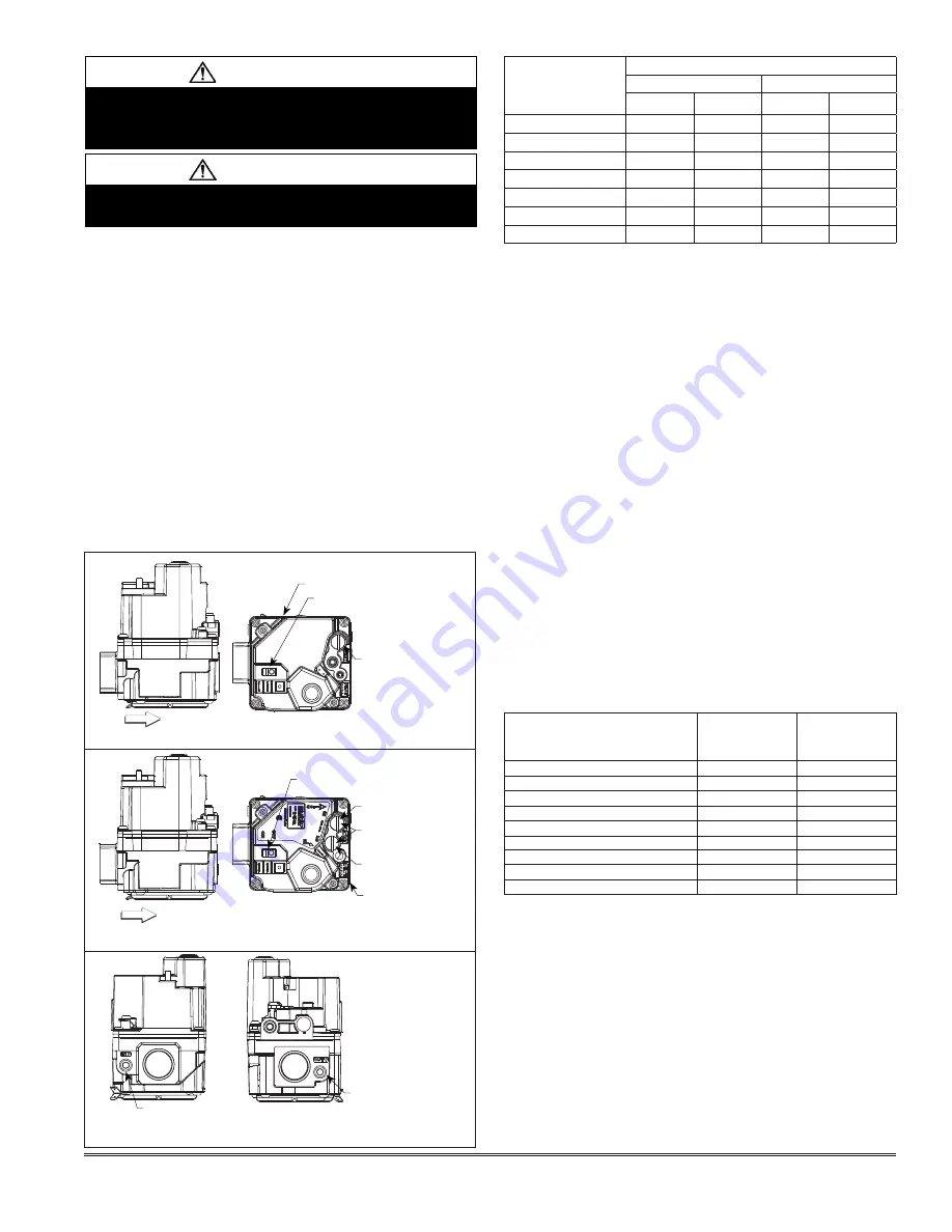
FIGURE 18 - WHITE ROGER SINGLE STAGE AND
2-STAGE 6H GAS REGULATOR VALVE
2-STAGE AND 5:1MODULATION OPTION
GAS FLOW
GAS FLOW
SPLIT MANIFOLD - 10:1 MODULATION OPTION
SINGLE STAGE VALVE
ON/OFF SWITCH
(SHIPPED IN OFF POSITION)
ON/OFF SWITCH
(SHIPPED IN OFF POSITION)
HIGH-FIRE
ADJUSTMENT
LOW-FIRE
ADJUSTMENT
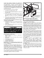
2-STAGE VALVE
INLET PRESSURE TAP
OUTLET PRESSURE TAP
MANIFOLD PRESSURE
ADJUSTMENT (SCREW
BENEATH CAPS)
MANIFOLD PRESSURE
ADJUSTMENT (SCREW
BENEATH CAPS)
unit calling for maximum rate (High-Fire) and allow
five minutes for the unit to reach steady state.
2.
While waiting for the unit to stabilize, notice the flame.
It should be stable without flash-back and should not
lift from the burner heads. Natural gas should burn
mostly blue with some clear yellow streaks.
3.
After allowing the unit to stabilize for five minutes,
record the manifold pressure and compare to the
value given in
Table 7
.
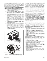
Proper Gas Flow
- To check for proper gas flow to burners,
determine Btuh input from the gas heating capacity table
(
Chart 4 on Page 46
). Divide the input rating by the Btuh
per cubic foot of available gas. Result is the number of
cubic feet per hour required. Determine the flow of gas
through gas meter for two minutes and multiply by 30 to
get hourly flow of gas to burners.
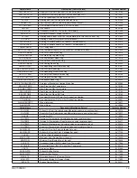
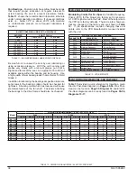
ALTITUDE - ft. (m)
GAS MANIFOLD PRESSURE - i.w.g. (kPa)
HIGH FIRE
LOW FIRE
EVT-12
EVT-09 thru
EVT-10
EVT-12
EVT-09 thru
EVT-10
0 - 2000 (0 - 610)
3.7 (0.92)
3.5 (0.87)
1.6 (0.40)
1.1 (0.29)
2001 - 3000 (610 - 915)
3.6 (0.90)
3.4 (0.85)
1.5 (0.37)
1.1 (0.28)
3001 - 4000 (915 - 1220)
3.5 (0.87)
3.3 (0.82)
1.4 (0.35)
1.1 (0.27)
4001 - 5000 (1220 - 1525)
3.4 (0.85)
3.2 (0.80)
1.3 (0.32)
1.1 (0.26)
5001 - 6000 (1525 - 1830)
3.3 (0.82)
3.1 (0.77)
1.2 (0.30)
1.0 (0.25)
6001 - 7000 (1830 - 2135)
3.2 (0.80)
3.0 (0.75)
1.1 (0.27)
1.0 (0.24)
7001 - 8000 (2135 - 2440)
3.1 (0.77)
2.9 (0.72)
1.0 (0.25)
0.9 (0.23)
TABLE 7 - HIGH ALTITUDE DERATE
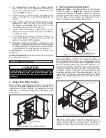
CAUTION
Disconnect heating demand as soon as an accurate
reading has been obtained.
CAUTION
For safety, connect a shut-off valve between the
manometer and the gas tap to permit shut off of gas
pressure to the manometer.
High Altitude Derate
- Natural gas units may be installed
at altitudes up to 2000 feet (610m) above sea level without
any modification. At altitudes above 2000 feet (610m),
units must be derated to match gas manifold pressures
shown in
Table 7
.
NOTE - This is the only permissible derate for these
units.
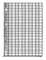
The adjusted high altitude input rate for the United States
can be calculated using the Derate Multiplier Factor listed
in
Table 8
. There is a difference between the United
States and Canada regarding derating for altitude:
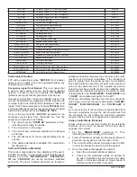
UNITED STATES
At altitudes above 2000 ft. (610M), the input rate must be
reduced by 2 percent for each 1000 ft. (305M) above sea
level.
See Table 8
for Derate Multiplier Factor and apply
as follows:
Example:
1. 100,000 Btuh input heater installed at 4300 ft.
2. Input rate at sea level x Derate Multiplier Factor =
input rate at installed altitude
3. 100,000 x 0.91 = 91,000 Btuh
ALTITUDE - FT (M)
PERCENT
DERATE
DERATE
MULTIPLIER
FACTOR*
0 - 2000 (0 - 610)
0
1.00
2001 - 4000 (610 - 914)
4 - 6
0.95
3001 - 4000 (914 - 1219)
6 - 8
0.93
4001 - 5000 (1219 - 1524)
8 - 10
0.91
5001 - 6000 (1524 - 1829)
10 - 12
0.89
6001 - 7000 (1829 - 2134)
12 - 14
0.87
7001 - 8000 (2134 - 2438)
14 - 16
0.85
8001 - 9000 (2438 - 2743)
16 -18
0.83
9001 - 10,000 (2743 - 3048)
18 - 20
0.81
* Derate Multiplier Factor based on midpoint of altitude range
TABLE 8 - ALTITUDE DERATE MULTIPLIER FACTOR
CANADA
At altitudes from 2000 to 4500 ft. (610 to 1372M) above sea
level the input must be derated 5 percent by an authorized
Gas Conversion Station or Dealer. To determine correct
input rate for altitude see example above and use 0.95 as
the Derate Multiplier Factor.
Burner Ignition Control
The Direct Spark Ignition Control is shown in
Figures 19
thru 22
, depending on the Gas Heat Option and the Unit
Model involved. It is manufactured by UTEC and provides
the following features:
Summary of Contents for ENERVENT+ EVT-09 Series
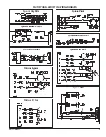
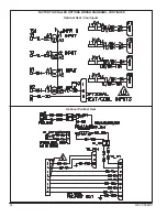
Page 30: ...30 REVT 05ERV UNIT WIRING DIAGRAM ...
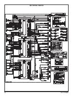
Page 31: ...REVT 05ERV 31 UNIT WIRING DIAGRAM CONTINUED ...
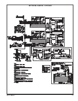
Page 47: ...REVT 05ERV 47 UNIT WIRING DIAGRAM XVIII WIRING DIAGRAMS ...
Page 48: ...48 REVT 05ERV UNIT WIRING DIAGRAM CONTINUED ...
Page 50: ...50 REVT 05ERV Optional Heat Cool Inputs Optional Pre Post Heat ...
Page 57: ...REVT 05ERV 57 DIAGRAM 15 5 1 MODULATION GAS POST HEAT DIAGRAM 14 2 STAGE GAS POST HEAT ...


