


26 REVT-05ERV
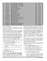
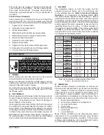
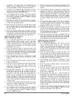
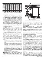
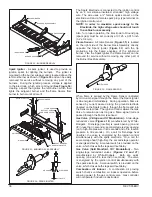
FIGURE 19 - 2-STAGE GAS POST HEAT OPTION
(FOR ALL MODELS)
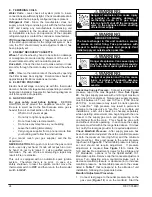
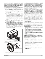
FIGURE 20 - 5:1 MODULATION GAS HEAT OPTION
(FOR ALL MODELS)
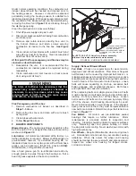
FIGURE 21 - 10:1 MODULATION GAS HEAT OPTION
(FOR EVT-36 THRU -12)
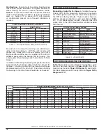
FIGURE 23 - NORMAL IGNITION SEQUENCE
FIGURE 24 - IGNITION ATTEMPT SEQUENCE
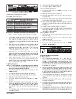
FIGURE 22 - 10:1 MODULATION GAS HEAT OPTION
(FOR EVT-36 THRU -88)
1.
Spark ignition of main flame and control of main gas
valve.
2.
Sensing of main flame.
3. Control of 2
nd
stage gas valve.
4. Sensing of system induced draft centrifugal or
pressure switch.
5. Sensing of high temperature limit and rollout switch.
6. Control of system induced draft motor.
7. Diagnostic LED.
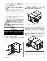
The unit will usually ignite on the first attempt; however,
the ignition attempt sequence provides three trials for
ignition before locking out. The lockout time for the
control is five minutes. After lockout, the ignition control
IGNITION CONTROL BOARD
FLUE BOX COVER
COMBUSTION AIR INDUCER
HEAT EXCHANGER TUBES
*ALUMINIZED (STD: EVT-09THRU -88)
*STAINLESS STEEL(STD: EVT-10,-12)
OPTION: EVT-09 THRU -88
COMBUSTION AIR PROVING SWITCH
PRESSURE TAP
2-STAGE GAS VALVE
FLUE EXHAUST VENT
BURNER RACK ASSEMBLY
IGNITION CONTROL BOARD
STAINLESS STEEL HEAT
EXCHANGER TUBES
GAS SUPPLY LINE
(
SEE FIGURE 9
)
2-STAGE GAS VALVE
PRESSURE TAP
MODULATION GAS VALVE
GAS HEAT CONTROL COVER
IGNITION CONTROL BOARD
GAS HEAT CONTROLS
(LOCATION FOR EVT-10 & -12)
STAINLESS STEEL HEAT
EXCHANGER TUBES
EXTERNAL CONNECTION GAS
SUPPLY
(SEE FIGURE 9)
MODULATION GAS VALVE
BLOWER ACCESS DOOR
GAS HEAT ACCESS DOOR
GAS SUPPLY LINE
(
SEE FIGURE 9
)
GAS HEAT CONTROLS
(LOCATION FOR EVT-36 THRU -88)
IGNITION CONTROL BOARD
GAS HEAT CONTROL MODULE COVER
SINGLE STAGE GAS VALVE
automatically resets and provides three more attempts at
ignition. Manual reset after lockout requires breaking and
remaking power to the ignition control.
See Figure 23
for
a normal ignition sequence and
Figure 24
for the ignition
attempt sequence with retrials (normal timings given for
simplicity). Specific timings for the ignition controls are
shown in
Figure 25
.
Summary of Contents for ENERVENT+ EVT-09 Series
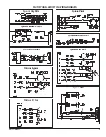
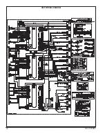
Page 30: ...30 REVT 05ERV UNIT WIRING DIAGRAM ...
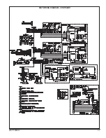
Page 31: ...REVT 05ERV 31 UNIT WIRING DIAGRAM CONTINUED ...
Page 47: ...REVT 05ERV 47 UNIT WIRING DIAGRAM XVIII WIRING DIAGRAMS ...
Page 48: ...48 REVT 05ERV UNIT WIRING DIAGRAM CONTINUED ...
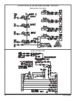
Page 50: ...50 REVT 05ERV Optional Heat Cool Inputs Optional Pre Post Heat ...
Page 57: ...REVT 05ERV 57 DIAGRAM 15 5 1 MODULATION GAS POST HEAT DIAGRAM 14 2 STAGE GAS POST HEAT ...


