


28 REVT-05ERV
energized. The Gas Valve and Combustion Air
Inducer remain energized for a 2-minute warm-up
period regardless of what the thermostat calls for.
7.
If a flame is not detected after first ignition trial, the
Ignition Control will repeat
Steps 5 and 6
two more
times before locking out the gas valve.
8. For troubleshooting purposes, an ignition attempt
after lockout may be re-established manually by
moving the thermostat switch to
"OFF"
and then
return to
"HEAT"
position
9. After burner ignition the unit will remain on second-
stage fire for a 2-minute warm-up period regardless
of what the thermostat calls for.
10. After this warm-up period, the unit will react to what
the thermostat calls for. If the thermostat calls for low-
fire, the inducer will drop to low speed and the valve
will go to low fire.
11.
When the building thermostat is satisfied and the
demand for heat ends, the Gas Valve is de-energized
immediately and the Combustion Air Inducer switches
to high speed for a 30-second post-purge period.
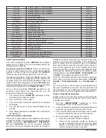
Heating sequence of operation
(MD-5:1 Modulating Option)
1.
On a call-for-first-stage-heat, "W1," "W2" and "R"
closes allowing 24vac to flow to "W1," and "W2"
circuits. The control board then checks to see if the
pressure switches are open. If either pressure switch
is closed, the control flashes "3" on the LED and waits
indefinitely for it to open.
2. When the pressure switch is sensed as open, the
control begins the pressure switch proving period.
The Ignition Control will verify that the pressure switch
is open and that limits are in closed position before
energizing the Combustion Air Inducer.
3.
The Combustion Air Inducer is energized on high
speed and the control waits for the pressure switch
to close.
4. When the pressure switch closes, a 30 second pre-
purge period begins.
5. At the end of the pre-purge period, the spark igniter
and the second stage gas valve high-fire are
energized. At the same time 24vac is sent to the
SC30 to start modulating.
6.
Burners ignite and carry over. Once the flame is
established and detected by the flame sensor all
the burners should be lit and the Spark Igniter de-
energized. The Gas Valve and Combustion Air
Inducer remain energized for a 2-minute warm-up
period regardless of what the thermostat calls for.
During the warm-up period the SC30 Control will
send a 20vdc signal to the Maxtrol Valve regardless
of the dc input.
7.
If a flame is not detected after first ignition trial, the
Ignition Control will repeat steps 5 and 6 two more
times before locking out the gas valve.
8. For troubleshooting purposes, an ignition attempt
after lockout may be re-established manually by
moving the thermostat switch to
"OFF"
and then
return to
"HEAT"
position
9. When the warm-up period expires, modulation of the
system is handed over to the Building Management
System.
10. If the building controller is providing an analog signal
between 2.0 and 5.3 vdc to the SC30 Control, the
system will continue to operate at low fire and low
speed Combustion Air Inducer. The modulation valve
will be powered proportionally to the input voltage
from the controller and will open or close, changing
the gas manifold pressure; which vary from 0.2 to 1.2
iwc.
11. If the signal increases above 5.3 vdc, the Combustion
Air Inducer switches to high speed and the high-fire
second stage Gas Valve is energized. The manifold
pressure will vary from 1.4 to 3.5 iwc.
12.
Operation will continue in high-fire mode until the
signal from the Building Management Controller drops
below 4.7 vdc. At this point the SC30 de-energizes
the second stage Gas Valve and the Combustion Air
Inducer switches to low speed.
13.
When the building thermostat is satisfied and the
demand for heat ends, the Gas Valve is de-energized
immediately and the Combustion Air Inducer switches
to high speed for a 30-second post-purge period.
Heating sequence of operation
(SP-10:1 Modulating Option)
1.
On a call-for-first-stage-heat, "W1", "W2" and "R"
closes allowing 24vac to flow to "W1," and "W2"
circuits. The control board then checks to see if the
pressure switches are open. If either pressure switch
is closed, the control flashes "3" on the LED and waits
indefinitely for it to open.
2. When the pressure switch is sensed as open, the
control begins the pressure switch proving period.
The Ignition Control will verify that the pressure switch
is open and that limits are in closed position before
energizing the Combustion Air Inducer.
3.
The Combustion Air Inducer is energized on high
speed and the control waits for the pressure switch
to close.
4. When the pressure switch closes, a 30 second pre-
purge period begins.
5. At the end of the pre-purge period, the spark igniter
and the second stage gas valve high-fire are
energized. At the same time 24vac is sent to the
SC30 to start modulating.
6.
Burners ignite and carry over. Once the flame is
established and detected by the flame sensor all
the burners should be lit. The Spark Igniter is de-
energized. The Gas Valve and Combustion Air
Inducer remain energized for a 2-minute warm-up
period regardless of what the thermostat calls for.
During the warm-up period the SC30 Control will
send a 20vdc signal to the Maxtrol Valve regardless
of the dc input.
7.
If a flame is not detected after first ignition trial, the
Ignition Control will repeat
Steps 5 and 6
two more
times before locking out the gas valve.
Summary of Contents for ENERVENT+ EVT-09 Series
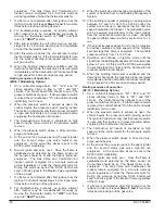
Page 30: ...30 REVT 05ERV UNIT WIRING DIAGRAM ...
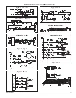
Page 31: ...REVT 05ERV 31 UNIT WIRING DIAGRAM CONTINUED ...
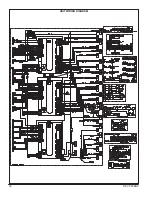
Page 47: ...REVT 05ERV 47 UNIT WIRING DIAGRAM XVIII WIRING DIAGRAMS ...
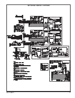
Page 48: ...48 REVT 05ERV UNIT WIRING DIAGRAM CONTINUED ...
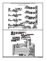
Page 50: ...50 REVT 05ERV Optional Heat Cool Inputs Optional Pre Post Heat ...
Page 57: ...REVT 05ERV 57 DIAGRAM 15 5 1 MODULATION GAS POST HEAT DIAGRAM 14 2 STAGE GAS POST HEAT ...


