


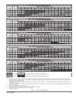
34 REVT-05ERV
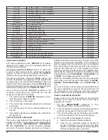
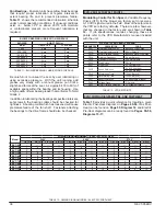
AIR FILTER SPECIFICATIONS
UNIT
SUPPLY AIR FILTERS
EXHAUST AIR FILTERS
QTY
W
H
D
QTY
W
H
D
EVT-09
EVT-19
2
18
20
2
2
18
20
2
EVT-28
EVT-36
2
20
25
2
2
20
25
2
EVT-46
EVT-62
6
16
20
2
6
16
20
2
EVT-74
EVT-88
6
20
20
2
6
20
20
2
EVT-10
EVT-12
8
18
25
2
8
20
20
2
TABLE 10 - SUPPLY AND EXHAUST FILTER SPECIFICATIONS
C. TEMPERING COILS
Cleaning Coils
- Coils must remain clean to maintain
desired performance. Inspect and clean coil at the
beginning of each season (cooling or heating). Heating
coils may be brushed or vacuum cleaned. Clean cooling
coils using a mild detergent or commercial coil cleaner.
Many coil cleaners contain harsh chemicals, so they must
bee used with caution by qualified personnel only. Flush
the coil and condensate drain with water taking care not
to get insulation, filters and air duct wet. Care should be
taken not to damage the coils, particularly the fins, while
cleaning. High pressure water should not be used due to
possible fin damage. If there is any doubt regarding water
pressure it is recommended that it be tested on a small
corner of the coil to determine if the fins will withstand the
questionable pressure level.
Drain Pans
- Drain pans in any air conditioning unit
will have some moisture in them therefore, algae and
other organisms will grow due to airborne spores and
bacteria. Periodic cleaning is necessary to prevent this
build-up from plugging the drain and causing the drain
pan to overflow. Also, drain pans should be kept clean
by qualified personnel to prevent the spread of disease.
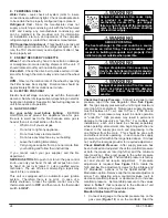
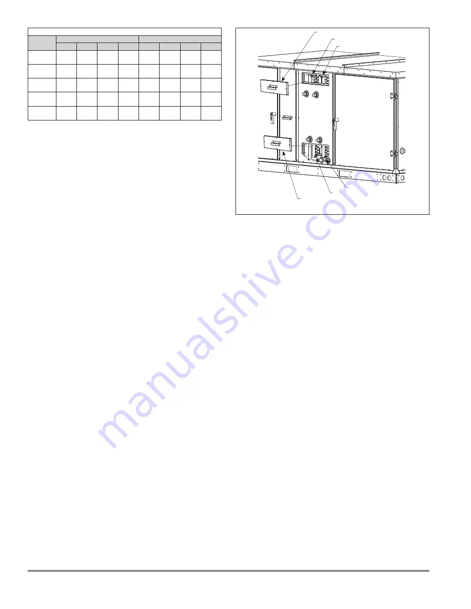
Winterizing
- Coil freeze-up can be caused by such
things a air stratification and failure of outdoor air
dampers. Routine draining of water cooling coils for
winter shutdown cannot be depended upon as insurance
against freeze-up. Severe coil damage may result. It is
recommended that all coils be drained as thoroughly as
possible (
See Figure 29
) and then treated in the following
manner:
1.
Fill each coil independently with an antifreeze solution
using a small circulating pump and again thoroughly
drain.
2.
Check freezing point of antifreeze before proceeding
to next coil. Due to small amount of water always
remaining in each coil, there will be diluting effect.
The small amount of antifreeze solution remaining
in the coil must always be concentrated enough to
prevent freeze-up. Carefully read instructions for
mixing antifreeze solution used. Some products will
have a higher freezing point in their natural state than
when mixed with water.
D. ENERGY RECOVERY CASSETTE (ERC)
Cleaning Wheel
- Over time, build up of material on
energy transfer surfaces reduces latent energy (water
vapor) transfer and reduces air flow. Therefore, periodic
cleaning is required to maintain building moisture control
and ventilation requirements. Frequency and method of
cleaning varies greatly with the application and amount
of run time. Use the following guidelines combined with
initial annual inspections to establish an appropriate
cleaning schedule.
Normal Indoor Environments
- In schools, office
buildings, or most homes, reductions in airflow or
effectiveness may not occur for five to ten years.
Moderate Occupant Smoking
- Measurable changes in
latent energy transfer and some loss of airflow can occur
in less than five years.
High Levels of Occupant Smoking
- In lounges,
nightclubs, bars and restaurants, latent effectiveness may
be severely reduced in less than one year, but without a
correspondingly severe loss of airflow
Industrial Applications
- Welding and machine
operations normally ventilate high levels of smoke or oil-
based aerosols that may result in a three to six month
washing cycle.
Tar and oil based aerosols condensing on the desiccant
surfaces eventually close off the micron-sized pores,
reducing the efficiency with which the desiccant can
transfer moisture. This reduces latent capacity, but does
not adversely affect sensible heat transfer. However,
this "Sticky" material builds up on the face of the wheel
bridging the narrow opening between parallel plates
reducing airflow, which does reduce sensible capacity
and ventilation rate. This "bridging" material can be
removed with a brush, vacuum or flat-bladed scraper.
Any loose particles that remain are subject to the self-
cleaning characteristics for dry particles; i.e., particles
small enough to enter the energy transfer matrix will pass
through, while larger particles attempting to enter are
blown clear as the wheel rotates into the counter-flowing
airstream
Restoration of latent effectiveness to near original
performance requires washing with water and alkaline
based coil cleaners. To facilitate washing, all Enervent
ERW segments are removable in minutes without the
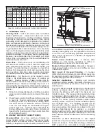
FIGURE 29 - WATER COIL VENT AND DRAIN PLUGS
VENT PLUG ACCESS PANEL
VENT PLUG - CHILLED WATER COIL
VENT PLUG - HOT WATER COIL
DRAIN PLUG - HOT WATER COIL
DRAIN PLUG - CHILLED WATER COIL
DRAIN PLUG ACCESS PANEL
Summary of Contents for ENERVENT+ EVT-09 Series
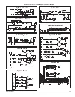
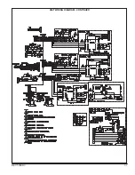
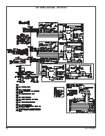
Page 30: ...30 REVT 05ERV UNIT WIRING DIAGRAM ...
Page 31: ...REVT 05ERV 31 UNIT WIRING DIAGRAM CONTINUED ...
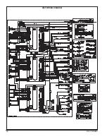
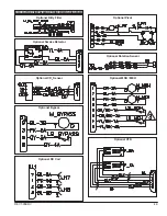
Page 47: ...REVT 05ERV 47 UNIT WIRING DIAGRAM XVIII WIRING DIAGRAMS ...
Page 48: ...48 REVT 05ERV UNIT WIRING DIAGRAM CONTINUED ...
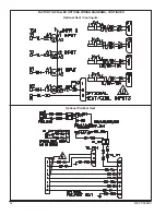
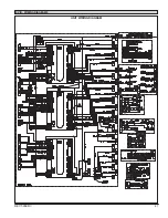
Page 50: ...50 REVT 05ERV Optional Heat Cool Inputs Optional Pre Post Heat ...
Page 57: ...REVT 05ERV 57 DIAGRAM 15 5 1 MODULATION GAS POST HEAT DIAGRAM 14 2 STAGE GAS POST HEAT ...


